The one from Amazing Synth is a really nice quality PCB and they will also sell you a pre-programmed PIC.
3 Likes
thats were I bought my PICs from .
3 Likes
Pretty sure this has been mentioned elsewhere, but… After mating my new case with my PCB, I have some adjustments to the BOM to suggest. The two top adjust trimpots, for offset and scale, these ones:
Should be changed to side adjust, otherwise you’re going to have to mark and drill a couple of holes. Alternatively, you could just modify the case SVG prior to having it cut. ![]()
2 Likes
Or adjust them before closing up the case. I haven’t seen a need to adjust them after that.
The main body of the trimpot is the same height as the stand-offs, so the little adjustment screws impinge on fitting the top nicely.
Let’s not mention the fact that mine are about 1mm off the PCB, which doesn’t help either… And let’s really not mention that I didn’t heed the warnings and soldered all the top side electrolytics vertically… ![]()
2 Likes
I think someone else might have countersunk some bits
Thanks for all the info on this thread. It was really helpful. The Module Tester/Noodle Toaster could really benefit from some verbose instructions. Personal take aways:
- Install KiCAD and grab @analogoutput 's version of the module_tester repo! I’ve repeatedly referenced it to answer questions along the way.
- Soldering resistors from above is a very handy technique!
- Always triple check the BOM, so you’re not having to pay the shipping tax each time you find another component that was missed.
- ~700F/370C is a good temperature for silver, lead-free solder, if you a mad man who insists on using it… like me.
- The nylon washers in synthcube’s enclosure are meant to go on the standoffs on the top side of the board. It’s mentioned at the very end of a thread on modwiggler. See Mutable Instruments Module Tester - batch CLOSED! - Page 10 - MOD WIGGLER
- Lenore Gilbert’s livestream videos were very helpful, but it’s good to watch them all the way through, as she makes some mistakes along the way.
- With Mutable Instruments now shut down, it was hard to track down the official docs (with calibration instructions) for the Modular Tester. Module Tester - Mutable Instruments prehistoric projects
- Wait and get clarification rather than charging ahead. This bit on amazingsynth, does, in fact, mean put the long pins of the LCD header UP through the bottom of the board, with the plastic block underneath the board: “I’d also recommend taking care soldering the header for the LCD screen on, if you put it the wrong way round your screen will be suspended 3mm off the pcb - much better to put it on so it lies flat against the board.”
- If you put the LCD header on wrong, DO NOT try to desolder and put it on the “right way” so it will fit properly in the enclosure. I accidentally cut traces on my board in the process, and now it’s garbage. Time to salvage the ICs, order a new PCB and component, and start over. long, painful & expensive sigh
I should have just left it alone:

At least I did have a functioning Module Tester for a couple of days. Hopefully, the next one I build will go faster now that I know what pitfalls to watch out for. amazingsynth mentioned that I might be able to get the board repaired. Any idea how I’d go about doing that, ideally in the Seattle area? Or at least how to get the TEL 5-1222 off so I can reuse it? I’ve removed most of the solder, but it won’t budge.
Thank again!
skinlayers
1 Like
I could probably help repair it. I’m familiar with the build, though in the end decided not to build it. I have a desoldering station and some experience with fixing damaged traces, and I’m near Bellingham, but I used leaded solder.
1 Like
That would be amazing! I’d be more than happy to bring it, and compensate you for your time and effort. It just seems like such a waste to chuck it in the trash when it was working. It’s the biggest soldering project I’ve built to date. I can’t find a DM system in this forum, so feel free to email me (my username at Gmail). I’m skinlayers on most platforms, except Instagram, where I’m skinrelays.
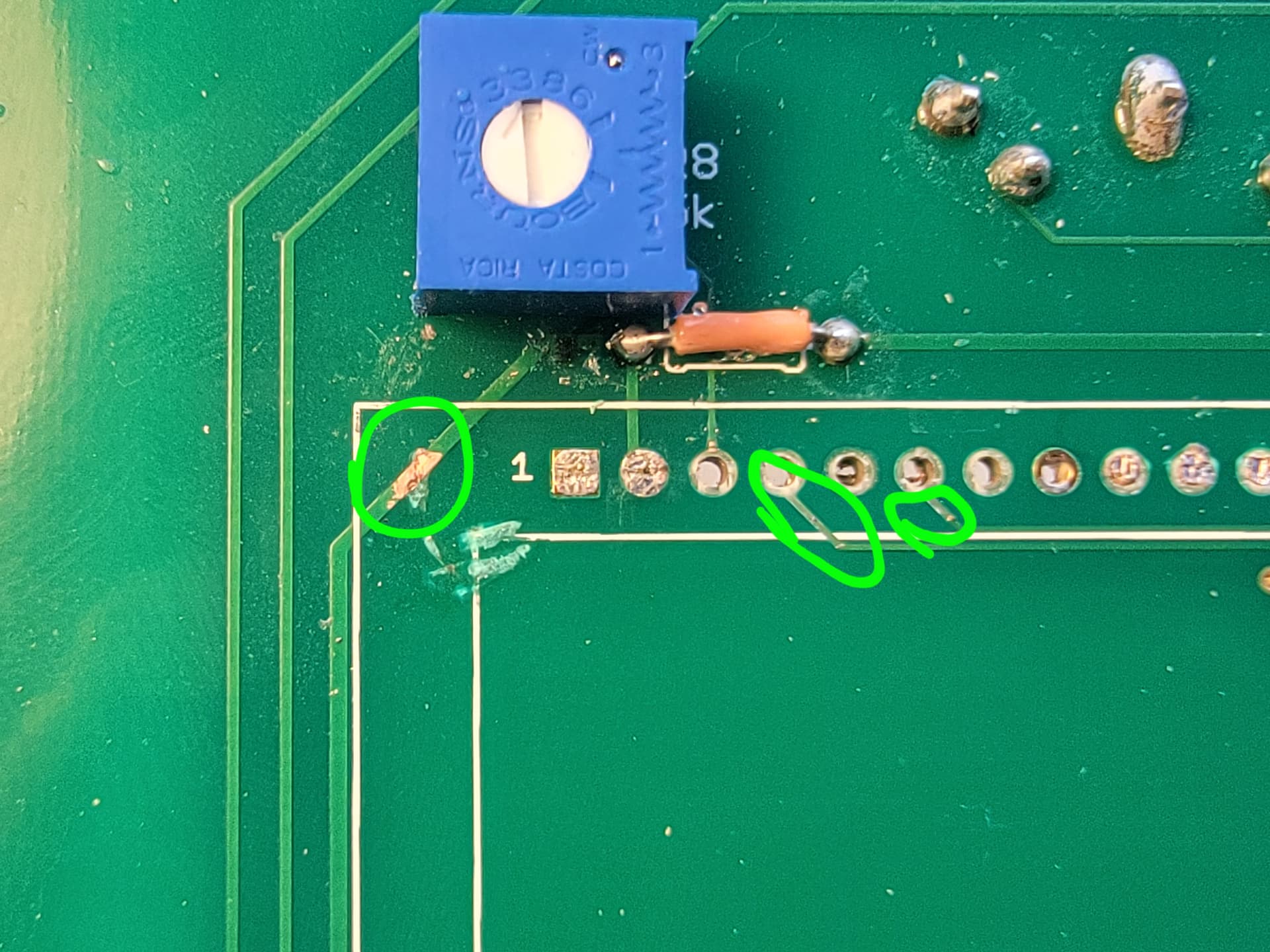
Edit: From what I can tell, I damaged 2 traces and “lifted” a number of pads on both the front and back of where the LCD pin header goes. That’s when I gave up and admitted defeat. The one on the left (+5V) is just exposed, and still passes a continuity test. The middle (LCD_RS) and right (LCD_ENABLE) do seem to be cut, not that there’s much of a pad left on either of them to test, but I only seem to get continuity when probing the cut area.
Even if it turns out that the board isn’t worth fixing, it would be nice to recover the TEL 5-1222, since that’s a $21 part. I’ve removed most of the solder from it, but it still doesn’t want to come off the PCB.
Thank you again!!!
skinlayers
1 Like
As mentioned on the amazingsynth site, there’s a cheaper ($13) alternative to the TEL 5-1222; its ripple spec is worse, but I haven’t noticed any problem using mine.
This site has DMs, but you’re probably too new to have the ability to send one.
4 Likes
Ah. That makes sense. I’m also currently limited to only one photo and two links per post, so lack of access to DMs makes sense.
Yeah, I saw the cheaper DC-DC Converter on amazingsynth. But, since I don’t understand the potential impact of a “more ripply” converter, I decided to stick to the original. If it is functionally the same, though, I may get it instead if I can’t have the board repaired and/or recover the converter.
Side note: Thanks for the KiCAD version of the schematics! I’ve referenced them multiple times through out this process.
1 Like
I swear by this stuff for all my soldering screwups.
They have lead-free but I’ve never used it.
1 Like
I added you on Instagram
1 Like
Would swapping out the LED’s on this for some 5mm red’s affect anything adversely?
I used lilac ones, didn’t seem to effect anything,…
1 Like
Thanks!
I am just putting this together and I think the last thing that I have to do is put in the resistor for the LCD display - but I’m not sure exactly which one to use. This is the model I have…
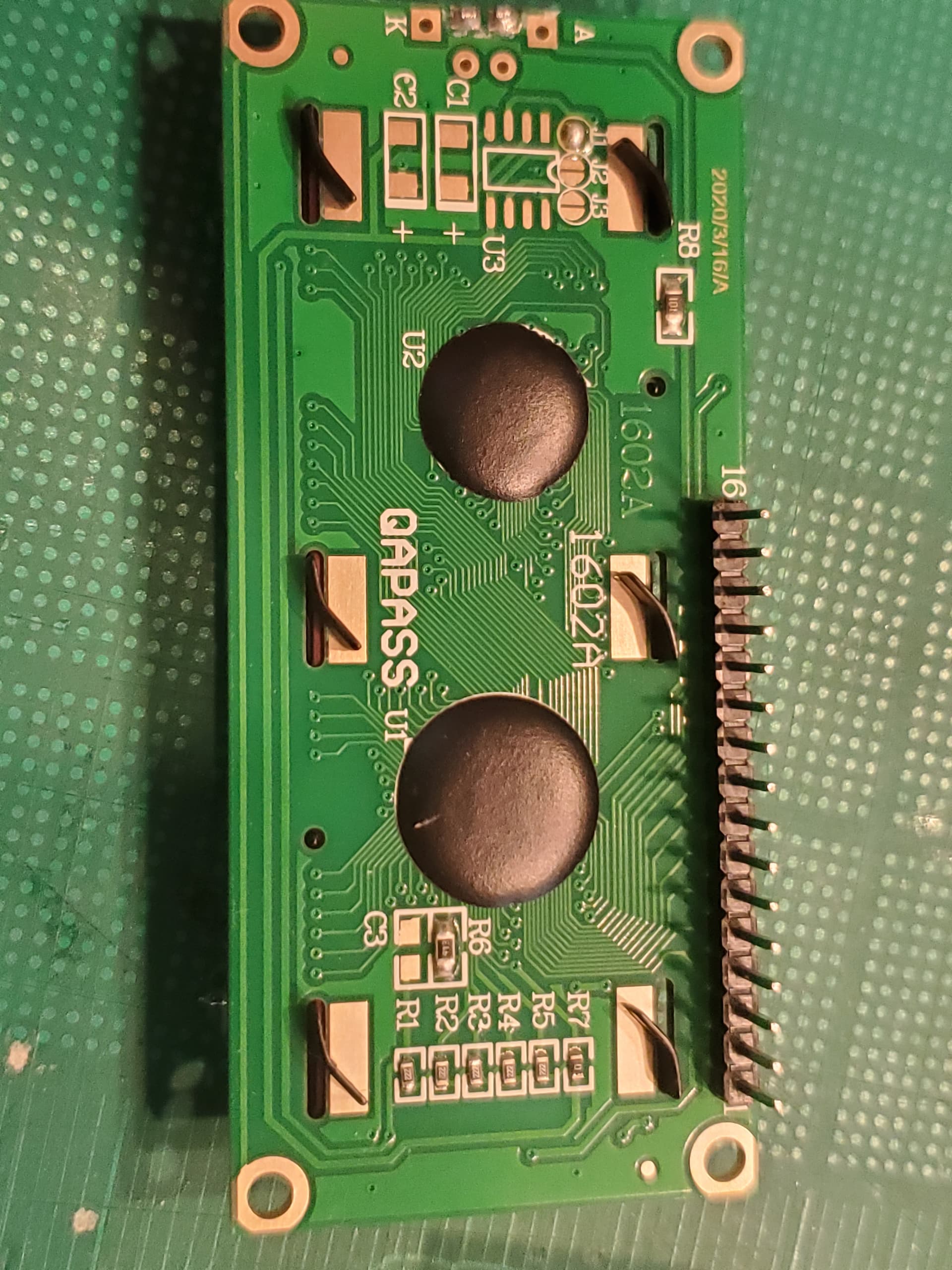
Yours has a 100R resistor (R8) on the board. This resistor is the current limiter for the LED backlight. It’s powered with +5 V. If you have a datasheet for the display it should tell you what the LED forward voltage is and its maximum current so you can work out if 100R is enough. But it probably is, they likely would not have put a 100R there if it was too small for a 5 V supply. If the forward voltage is ~ 3 V then 100R would give (5-3)/100 = 20 mA, which is probably OK.
2 Likes
lots of people use a wire link
1 Like
I finally got everything soldered up for my module tester, powered it on, and… one LED turned on (the Clk out) and nothing else. Well, kind of. It turns out that my LCD was on, but with no backlight, and the contrast was tuned wrong. When I figured that out I started looking for the problem with the backlight. When I stuffed the board I thought (wrongly) that I needed either the contrast trimmer OR the zero ohm resistor, not both. Well, you need both, and the backlight wasn’t getting power.
Backlight working, I started playing with it and quickly realized that it was still not working right. The Clk out LED is still on, but none of the other buttons are doing anything so I can’t change the mode. I figured because of the way the buttons went in they could go either way around. I haven’t tested this theory yet, but I’m pretty sure they’re going to work like every other tact switch ever.
My guess is that there’s something wrong between the buttons and the MCU. It’s likely not the resistor network, so my guess is either the 74HC165 shift register is bad, or there a bad solder joint on the MCU where the serial signal connects, or maybe one of the ground connections. Troubleshooting will commence at some point this week. Any thoughts are appreciated.
I am working on my own right now - I did a smoke test the other day and then found out that I am missing OK1. Somehow I ended up with double of all of the IC’s except for that one (and the big main chip - here’s hoping I don’t blow THAT one up!!). I put in another mouser order with the missing IC as well as yet another load of jack sockets.
At least the LCD came on and there was no smoke!
I’m still designing the case for 3d printing as well.
1 Like