There was a claim that the EU had banned AC/AC adapters which I countered by pointing out the Belgian rs-online site has them for sale. But there seem to be none on the Australian rs-online site.
I remember reading about the ban on Rod Elliott’s website. If I am reading this correctly (and most likely I am not as this is a long piece and my memory is hazy) there is a ban in place, but AC transformers have gotten an exception under certain circumstances. If anyone’s concerned and have enough patience to go through the long polemic article they can probably figure out whether the particular AC/AC wall-wart conforms to the rules to be able to fit under the exception.
It appears it isn’t a ban on linear supplies, it’s a maximum current for adapters that effectively bans transformer based adapters. But at the top it says
The regulators were finally convinced that AC/AC external supplies must use a iron-core transformer, and the requirements were removed for these to have extremely small no-load power consumption. … Everything else described below remains unchanged - the only thing that is different is that the ban is in place, and with the possible exception of some (very) old stock, the supplies available now are MEPS compliant. AC/AC supplies still use iron cored transformers (as they must).
which sounds to me like AC/AC wall wart transformers are still legal. (IANAL)
I think I mentioned this earlier in the thread, but I essentially DIY my own wallwart (safer than it sounds).
A couple of the AC/AC wallwarts I’ve had have been noisy and vibrate horribly. One died prematurely, they don’t seem well built generally.
You can pick up toroidal transformers easily here in the UK to do the same job.
In my latest build, I enclosed one in a plastic Hammond case that was external to my build. I used a 3 metre IEC cable that I cut in the middle, and used wago connectors to connect the mains plug side to the transformer primary, and the transformer secondary to the IEC male connector.
Wago connectors are used for mains electrics in homes over here, so figure they should be adequate for this.
I also connected the protective earth via a wago connector, which is then taken via the IEC cable straight to a bolt on my metal front panel.
I left the fuse in the IEC plug, and added a 3A fused IEC connector to my case (the transformer was overrated at 6A, which is a totally unnecessary amount). I’m only taking 12VAC to the synth itself, and any metal is connected to the mains earth.
I’ve seen UK toroidal power boards on the usual Aliexpress etc. That said if working with or using mains AC scares you (and it should) find a friendly electrician (my friend Al did all my testing and certifications so i could use the kit in schools. Cost? Im his unpaid guitar tech/b’tch)
On the primary side, the wiring is intuitively coloured. For use at 230v you connect the grey and violet wires together.
The IEC cable when cut will (should?!) have three wires in it, blue, brown, yellow/green. On the plug side, you connect brown from the plug to brown on the transformer, blue from the plug to blue on the transformer. The yellow/green cable bypasses the transformer, so connect each side back together.
On the secondary of the transformer (there’s two in this case), you connect the hot cable (either red or yellow) to the brown cable on the IEC male side, and 0v (either orange if you chose yellow, or black if you chose red) to blue.
I used these to make the connections:
And this for the input into the synth:
6A is too much in the sense that my build doesn’t draw anywhere near that, or anywhere near 3A really. I put in a 3A fuse but you could go lower/higher as needed.
You should absolutely treat mains current with respect. If you don’t feel comfortable, don’t do it.
My new power system seems to be working. Laptop PSU distributed to meanwell dc/dc converters. One laptop PSU should safely power 6 of the 30w converters, for 7.5 amps each on 12v and -12v rails. I am trying this so I can isolate troublesome modules on their own converter. They have ground isolation, but I am not sure that matters once I connect a patch cable from another module. Not a cheap system, but I have several laptop PSUs lying around.
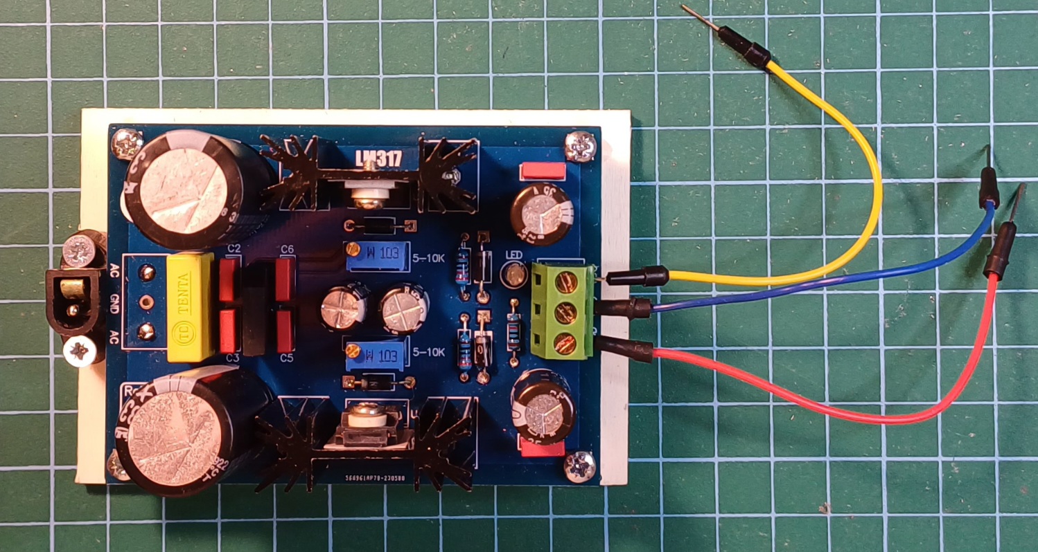
I still can’t find where I’ve put all those extra PCBs, regulators, and capacitors that I’ve set aside for building additional power supplies, so, in the meantime, I got this kit to build one for my desk to test new modules.
Problem is, that I only realized that this particular design requires a transformer with a center tap which I don’t have. The PCB, however, has a bridge rectifier on board so I think that a center tap is not necessary here. The build, however, does not work at all.
Before I look into possible issues in the build, I wanted to ask those more experienced with this design whether am I right to about not needing a center tap in a design with a bridge rectifier.
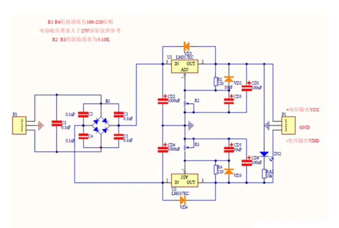
Thanks! Just to double check. B1 between C2/C3 and C6/C5 is a bridge rectifier, so I just connect gnd and AC to the AC wallwart transformer instead of the two AC inputs? When I connected the two AC inputs on the transformer I was also wondering whether that beefy capacitor on the left is really needed…
Typical stuff from our favourite auctions site with no documentation whatsoever. It’s simple enough, but I haven’t worked with a centre tap and a bridge rectifier before, so I am not quite sure what I am doing here!
Yes it’s two half-wave rectifiers. The positive part of the wave gets rectified into the positive rail, the negative into the negative. The two beefy caps (which don’t seem so beefy to me) are there the smooth out each of the rails.
Check the output of your transformer though. If you’d want +/-12VDC out of this, you want a 12-15V transformer, not 24V.
which absolutely is designed for a center tap transformer:
The transformer should be a center tapped type with voltage and current according to your needs, and these integrated voltage regulators cannot work with voltage above 35 VDC.
This kind of circuit would work with either a single 12VAC transformer connected to AC1 and GND, or a centre-tapped 24VAC transformer. When using a single transformer, the ripple will double, so it’s definitely not preferable. But it should work in a pinch. I was asking you to check the output rating of your transformer. If you’re rectifying 35VAC into 12VDC, you’re dumping a lot of power into heat, would not recommend.
The ‘documentation’ seems to suggest you can use a 35VAC transformer and get 1.25VDC out at 1A. That’s 2 x (35V x sqrt(2) - 1.25V) x 1A = 96W to heat. Those poor little heat sinks…