You can also avg the two since you already have the data for it. See if that helps when comparing to the threshold. If it’s still an issue, persist the avg you calculated as the “prev value” and check more times.
This becomes effectively a simple moving avg with a sample size of 1 offset. Increase the sample size form more smoothing, but you might not need it. The sample size would also mean persisting more values.
One more question: Why use a different RC combination for the second pole? Both have the same cutoff (~33kHz), but the second one uses a larger resistor and lower capacitance…
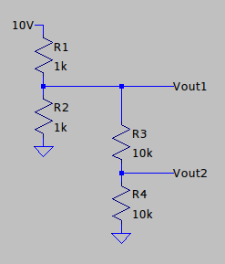
It’s similar to this: Suppose you have this voltage divider:
Vout is 5 V. But now if you decide you want both 5 V and 2.5 V and try to do it this way:
it doesn’t work; you get Vout1 = 4k, Vout2 = 2k. There are two ways you can think about this (really equivalent). One is a voltage divider only works perfectly if there is no current from the middle (or realistically, small current compared to what’s going through the divider), but here we’ve added a path to ground from the middle of the first divider so there is current. The other is we’ve added 2k in parallel with the 1k on the bottom of the first divider, making it effectively 1k||2k = 667Ω and changing the divider. But if you do this:
then either you’ve reduced the current from the middle of the first divider by a factor of 10, or you’ve made the bottom resistor effectively 1k||20k = 950Ω, and you get Vout1 = 4.88 V, Vout2 = 2.44 V. Not perfect but close.
An RC filter can be thought of as a voltage divider, but instead of DC resistance the capacitor has AC impedance whose magnitude is 1/(ωC) where ω is the frequency. Loosely, the capacitor acts like a small resistor for high frequencies and a large resistor for low frequencies. So with the capacitor on the bottom the output is near zero for high frequencies and nearly the same as the input for low frequencies: It’s a low pass filter. But again, its behavior changes, the cutoff frequency is different, if there is current flowing out of the middle. So in a two pole filter, to keep the same behavior for the first stage, you have to use larger “resistances” (impedances) in the second stage to reduce that current. A smaller value cap has a higher impedance, so increasing R and decreasing C reduces the current while keeping RC the same.
In the ARP envelope follower there’s a passive 4-pole filter where each stage is 10x the resistance and 1/10 the capacitance of the previous one. In the Kassutronics quantizer there’s also a 4-pole filter with 4.5 times the resistance and 1/4.5 times the capacitance in the second stage, then an op amp buffer, and then two more stages and a buffer which copy the first part — the buffer is another way to isolate one stage from the next and stop current flowing.
That’s why I was surprised to see in Hagiwo’s designs a 2-pole filter where the impedances in the second stage were comparable to or even smaller than the first stage. Not that it won’t work, but it will change the cutoff for the first stage.
Great explanation as always! Thank you! I guess you could get around it by putting a buffer in between, but then why not go the whole way and build an active filter?
add a trigger, so I can use it as a complete voice when I program an enveleope
output Filter still needs to be tested and values chosen.
no labels, because this can be a ‘universal mozzi module’, but I plan to have freq, color and decay, (color would be the chord type in chord mode, second operator in fm mode, etc.)
added 4 leds and a button, to select e.g. wave form for chords, ‘banks’ for drum mode(?)
I’ve been planning something similar. Is that regulator needed, the one in Arduino itself should be enough?
Couple of days ago I dived deeper into the Mozzi code, there’s quite lot problems and inconsistencies there. I would like to re-write many things of it, and actually fork it into a Arduino Nano -only version to make things clearer. If I want to do things with more processing power and pure floating point math, I’d probably just use Daisy.
Probably not, I had a problem when I used the internal regulator on the nano once: the nano got very very hot, but I guess that was a defect on that unit. I added this small solder bridge which says "use arduino regulator. So, if you want to use the internal regulator you can leave out the lm7805 and the two capacitors and just solder that bridge and then 12V is connected to the Arduino Vin
And yeah, Daisy would be nice, but I think that’s too much new stuff for me xD
I’ve been playing with the daisy, and it is quite nice to work with. It did force me to learn C++ to avoid issues with the daisyduino code. I am planning on designing a Kosmo module around it, but it is not on top of the priority list.
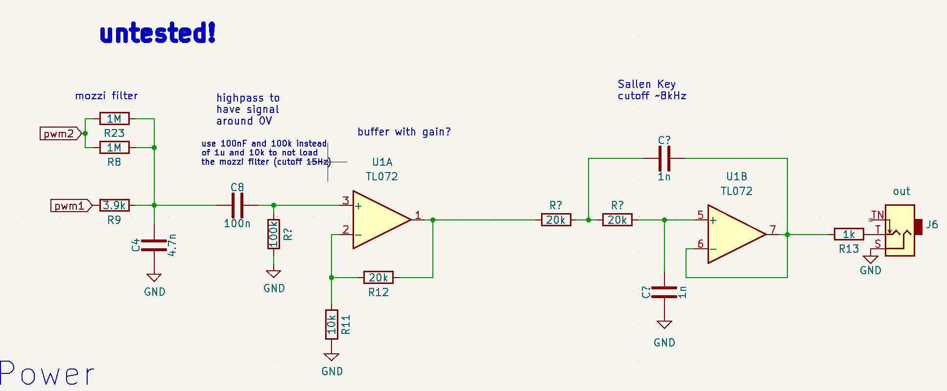
If I were doing it I’d start with the single pole filter recommended in the Mozzi docs, and if more filtering were needed to remove sampling artifacts I’d maybe add or switch to an active Sallen-Key filter tuned to around 8 kHz, about half the sampling frequency, watching for impedance problems. (You do have an unused op amp…)
@Krakenpine is that similar to what you had in mind for you next iteration? @analogoutput:
I was wondering how I determine the values for the Sallen-Key filter when I have a given frequency, like, should I use larger of smaller capacitor values? I guess in this setup I don’t need to think about loading the previous stage, because it is an opamp buffer?
Also: I want to add some gain, because the Arduino output is 0V to 5V only and there is the passive filter. Is there a difference whether I add the gain to the first opamp (buffer) or if I add it to the Sallen-Key filter?
Yeah, basically just that. I’m not sure if you can add gain to the Sallen-Key filter without messing it up, so just have the buffer before it amplify the signal. And with non-inverting amplifier that 20k&10k would already make the signal to be 15 volts peak to peak.
Right, the buffer output impedance is very low, so that’s not a concern. 20k resistors I’d think would be fine.
For maximum flatness in the pass band you can change the capacitors to get a Butterworth response. See calculator here. For 8k with 20k resistors it calculates 1.4 nF for the feedback cap and 0.7 nF for the cap to ground. 1.5 nF and 680 pF would be nearest standard values.
I’m curious, how much difference does adding the Sallen Key make? And could you use a higher cutoff on both it and the passive low pass? If the goal of the S-K is to further filter the sampling (16 kHz) and PWM (32 kHz), given that it’s a total of 3 poles versus the 2 poles of Hagiwo’s design maybe the cutoff doesn’t need to be as low.
Which is kind of high, reducing the 20k to 10k might be better.