I have a nte312 to try when I get back around to it.
1 Like
(It’s been 4 months? Sheesh.)
2 Likes
If I may butt in  This is a concept I’ve used before - preset integrators.
The schematic is based on a standard quadrature (Sine/Cosine) LFO. When the SYNC input is at 0V, the switches are switched to let the oscillator do its thing. When SYNC is switched to 5V, it disengages the oscillator circuit and puts the 10k resistor pairs across the integrators. The rightmost one charges to +5V, because the 10k resistor is connected to -5V. The middle integrator charges to 0V. When SYNC is released, the oscillator starts oscillating at those voltages. It’ll take a few tens of miliseconds for the 10k resistors to charge the 1u capacitors.
The integrators can be charged to any voltage you want too, just note the output voltage will be the negative of the input voltage – it’s an inverting amplifier afterall.
I’m working on a voltage controlled version of this circuit as well. I need to build it (it’s in simulation at the moment) but we’ll see!

1 Like
I’ve found that J109’s work best - they’ve got a 12Ω Rds-on compared to the 50 or 100 of the J112/J113.
On my LK13700 tri/pulse LFO I added a re-trigger by putting the gate signal through an edge detector and then using an open collector comparator to drive the gate a J109 that shorts out the integrating capacitor. The OC comparator allows me to drive it from -12V to 0V easily.
I also added a kind of sync to my VCO based on Hal Chamberlin’s circuits - again using a comparator - this time I hijacked the strobe pin to do the job, as the LM311 was already doing saw reset duty - something like this:
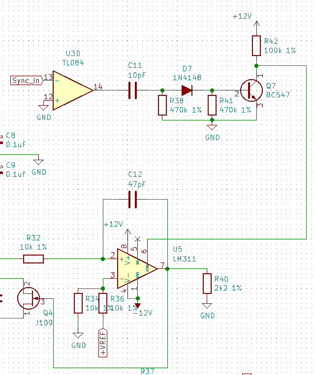
Need to build a second VCO to really try and use it, but it seemed to work okay when I was driving it from the function generator.
Cheers
2 Likes
I did a video about this:

4 Likes