Hi. This is a noob question I think, but since there’s some fine experts here I’m not afraid to ask a stupid question, since I want to understand better what I’m doing.
I’m prototyping the 4xDecay by Barton Musical Circuit. Simple, efficient. It’s working great.
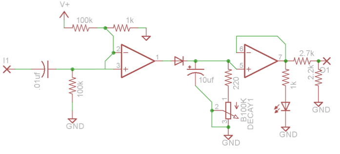
I want to add an amount control at the output so I change the original circuit from this …
Can I replace my 10k resistor before the output variable resistor by a 1k? I think I’m understanding that the purpose of this resistor and the one before the LED are too “split” the signal between the LED and the output?
Putting a variable resistor at the output is it enough to make this “amount control”? Should I add an op-amp to buffer it and a 1k resistor right after?
Thanks by the way. I hope I post in the right section of this forum.
Cheers!
The purpose of the 1k resistor is to limit the current through the LED.
The 2.7k and 2.2k resistors are configured as a voltage divider to reduce the voltage level from 12V to ~5.3V. You can increase or decrease the output voltage by replacing the 2.2k/2.7k pair with a potentiometer set up as an attenuator, correct. I don’t see why you have put the 10k resistor there, you can leave that out. However, to keep the output impedance low, you should buffer the output from the attenuator with a voltage follower op amp connected in series with a 1k resistor.
TLDR: remove the 2.2k/2.7k pair, replace with an attenuator, then buffer and add a 1k output resistor.
The purpose of the 1k resistor is to limit the current through the LED.
My bad, of course.
TLDR: remove the 2.2k/2.7k pair, replace with an attenuator, then buffer and add a 1k output resistor.
Awesome. Thank you a lot.
Just to explain the 10k resistor : I tested to replace the 2.2k/2.7k couple with just a potentiometer BUT when I tested it, when the potentiometer was has its minimum state (the output of the op-amp pin 7 directly connected to GND and nothing in the output) the LED stopped working and my VCOs were out of tune. Maybe it’s a consequence of a missing voltage follower?
Which op amps are you using? The TL07x series is supposed to be able to withstand being shorted to ground.
Anyway, to fix this you can connect a smaller resistance of 1k or so between the leg of the pot and ground. This’ll make sure there’s always at least 1k from the output to ground. If I’m thinking correctly, one of the pitfalls of this method is that your output will never be able to reach zero. Can anyone else back me up on this?
Edit: what was I thinking? Replace your 10k with a 1k and you’ll be good to go.
Between pin 7 and the attenuator input. Your diagram is correct but replace the 10k with a 1k, add a voltage follower after the pot, then another 1k on the output.
Between pin 7 and the attenuator input. Your diagram is correct but replace the 10k with a 1k, add a voltage follower after the pot, then another 1k on the output.
As mentioned above the original 2.7k and 2.2k resistors form a voltage divider. With a voltage V at the top and ground at the bottom, the junction between the two has the voltage reduced by a factor of 2.2k/(2.2k+2.7k).
The potentiometer, once it’s correctly wired as @eric points out, is a variable voltage divider. Voltage V is at the top and ground is at the bottom, and then if there’s x resistance on the bottom and 100k-x on the top, at the wiper the voltage is reduced by a factor of x/(x+(100k-x)) = x/100k.
My own preference is to have attenuators on inputs, not outputs, partly because putting attenuated signals over patch cables just makes things that much more noisy, and partly because, as mentioned, just putting an attenuator on the output increases the output impedance. You could use a 10k pot instead of 100k which would help, and be less noisy, but you really want ~1k on the output. I’d say use a 10k pot and follow it with an op amp buffer, but that does bump up the parts count and PCB real estate.
On the other hand, typical input impedance is ~100k which could be the value of an input attenuation pot, and usually no additional buffer needed.
The exception of course is a module intended to go into something that doesn’t have input attenuators, or to external equipment that’s expecting smaller signals than synth level. Then output attenuation makes some sense.
My reason for preferring input attenuators is even simpler…
If I plug an output into several inputs (via a mult…), I most probably want different attenuations on each one.
The technical reasons invoked by @analogoutput are a bonus.
Thanks @eric & @analogoutput for your answers! Yes, I always mess up with the direction of the resistor. If I understand well, when using a pot as an attenuator I should always put the output at the middle pin. Gotcha.
So Yay, about the input or output attenuator thing, I’ve never thought about this signal to noise ratio thing. It’s true that letting an attenuated signal flowing trough the patch cable might add noise some noise here and here. So, ok, it explains why all the modules have attenuator for their CV controls instead of their output, makes totally sense. And yes @eric you make your point about the mult thing. But yeah, I built my mult with attenuators at each output
I just think about a particular case : if you want to put an this decay into the 1v/oct of a VCO (to make some drummy sound), usually you don’t put attenuator on CV input of a VCO … Ok I just try to defend myself here.
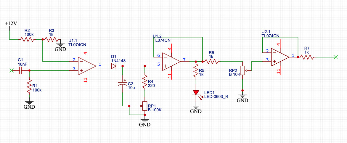
BTW here’s a corrected version of my schematic for those who might get lost here
Thanks!
I think this 4xDecay will be my last with output attenuators (I already drilled the panel so, let’s finish it this way)
I plan to build an entire new modular system (I mean, VCO + VCA + ADSR + LFO … and so on) in a bigger case so now I will think about the input attenuator and not the output!
Interesting thread, I’m glad I asked those questions!