If mine IS working correctly, should i not be able to connect my oscillator into the “forward” or “reverse” jack and get output out of the cv or the steps? Or i guess one could run the cv out into the oscillator input voltage (i have not tried this yet, so far my oscillators are on +12v system voltage)
So far i get only a low buzz out of the sequencer no matter the combo i plug in the oscillator /amp - while stand alone (without the sequencer) the oscillator sounds luvely! So knowing just how to plug in to test the sequencer will help me debug whatever is going on
The CV out of a step sequencer will give you a voltage, so not a sound. It will be something like 1.2Volt, and then 1.5V on the next step.
The CV out is used, typically, to drive the VCO (oscillator) and tell it which “note” to play.
So CV out is input for the VCO.
The step sequencer is usually excpeting a clock signal as input signal (so I would assume, the forward and reverse in this case).
The low buzz you get is probably because you are driving the step sequencer really fast (frequency of the VCO).
Hope it helps. Once you 'll get familiar with the name/meaning of things it will be easier.
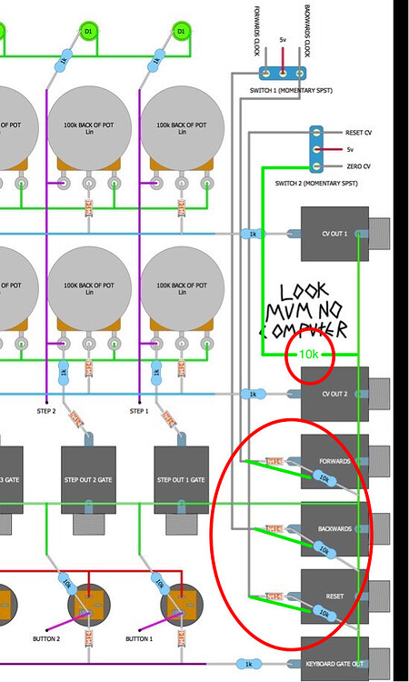
These 2 tell the sequencer to move forward to the next step (and loop to the 1st step at the end) or in reverse direction to the previous step (and loop to the end at the 1st step). The output correspondingly ‘connects’ to one of the 8 potentiometers and reflects its voltage each step of the way.
can someone give some kind of confirmation if this is the suggested schematic now or not with an extra pull down on the zero and connecting the resistors after the diodes? seems last one to ask as far as i can see, Fish, seems to have never gotten an answer - thanks for all of your help!
While combing through my modules I figured my sequencer could use some love.
I have not really been using the switch function that currently exists on it and I thought having a gate to trigger and a mute on the gate would be handy.
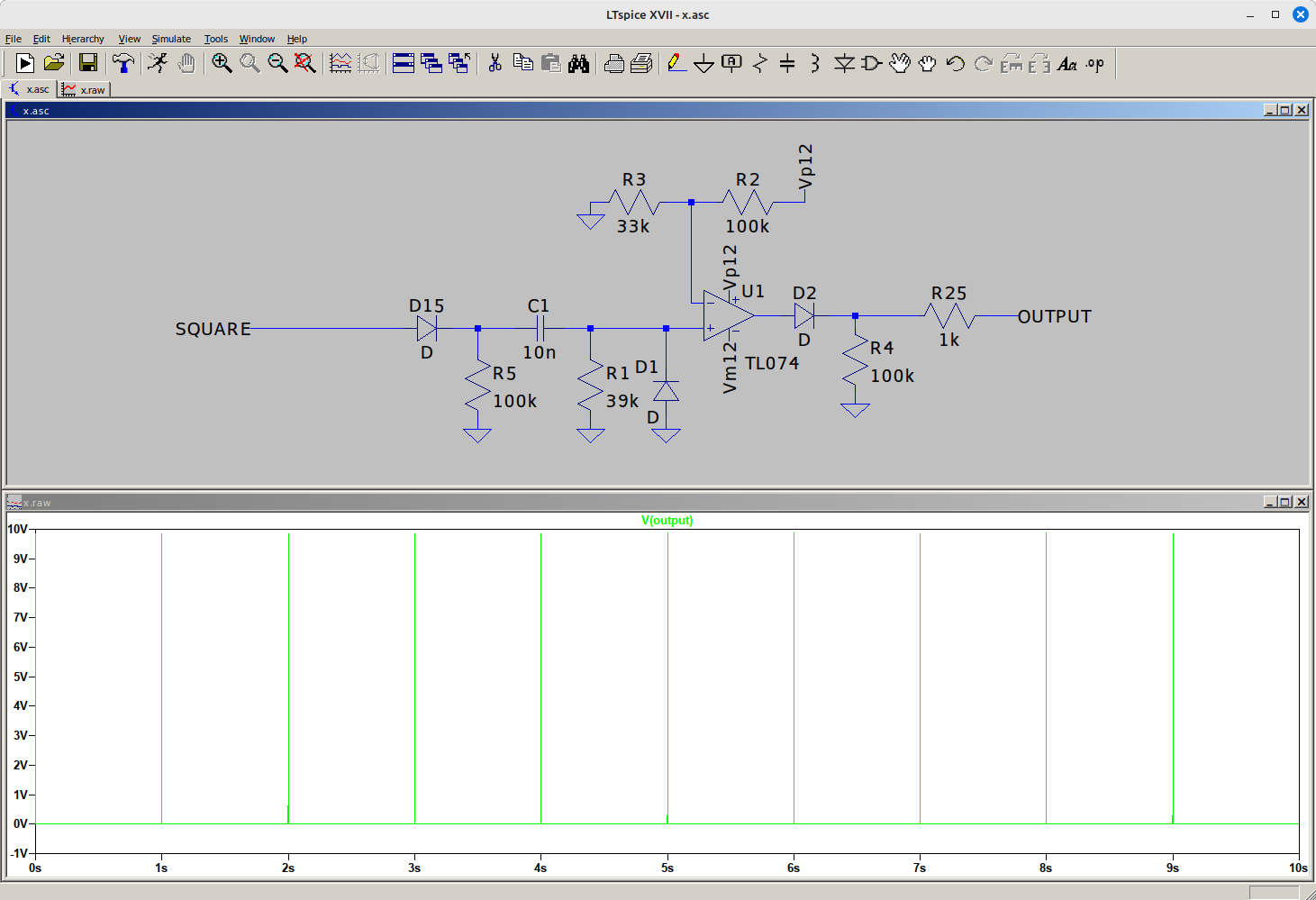
I wonder whether this works the way you would like it to.
Imagine there in an output pulse on D15, then the 10n capacitor will be charged. Next if the pulse on D15 is over, the capacitor remains charged, because it can not get rid of its charge because D15 is blocking. The resistor and diode on the input of the opamp will not help in that regard. So … It will probably produce one trigger signal and then no more (unless the diode or the 10n capacitor are of a leaky quality and the C discharges itself).
If you connect the Gate to Trig before D15, then the rest of the circuit might discharge the capacitor. I don’t know the rest of the schematic, so you will have to investigate that yourself.
Also, I think R25 should move to just before the output jack, for current limiting protection of the op amp as well as D15 and the added diode. And I’d add a 100k pulldown after the new diode too. The downstream module probably gives a high impedance path to ground, but on the off chance it doesn’t a pulldown there will make the difference between the diode working and not working.
Hi!
so we have finally got our build to a good level after quite some tinkering and learnings and made what we believe to be something a bit fun we thought we could now share - basically we included a controllable/customizable auto mode (clock) in the 8-bit sequencer!!
Automode includes some different variations including:
a. all steps (1-8)
b. only steps chosen (say 2,3, 5, 8)
c. steps recorded in the order they are pressed via a recording function that allows the user to key in up to 64 steps via the keyboard (played back according to BPM set or actual timing as pressed that can also be sped up or slowed down)
All of these auto modes are speed controlled by the forward/reverse switch/inputs
Automode is entered in really two ways, one holds down forward or reverse for +2seconds and it starts to run then to adjust the variant one holds down one or more buttons (one allows you to record up to 64 steps) for more than 5s or as you hold a button or buttons you hit the zero switch
Further, we made it so that the user can reverse the pattern by holding forward/reverse and hitting zero when in automode
you can find the code here, along with some instructions and a gif of our unit with a recorded auto:
we have some ideas for further expansion but we will see how much further we get but feel it has come far enough to get some feedback - what do you all think?
Finally, we are interested to see how it works for others - feel free to give it a go! if you do so, please make sure you verify the pinouts to match yours and let us know if it works for you and what arduino you have used!
here is the gif of it running a recorded sequence!!
the spaghetti junction and switch to the right are to allow program updates as we use some of the same pins in the for the sequencer as are needed to read&write:)
thank you so much! there was something else of yours that i wanted to make and clicked on but had the same result. wav trigger or big button? it will come to me
The wing nuts on the hinge are temp. until my countersunk head machine screws arrive. didnt have anything but button tops. i messed up by putting the pots in first and then didnt have quite enough space for the arcade buttons to be side by side. this was the obvious solution.
(the LED are inside the buttons…figured it would help save space but i havent tried wiring it yet. may be a headache idk)
sorry for another silly question…ive managed to figure everything out from the schematic all except im not sure where button 1 output would go since the rotary is in the usual spot…am i just not understanding how it works and its not needed?