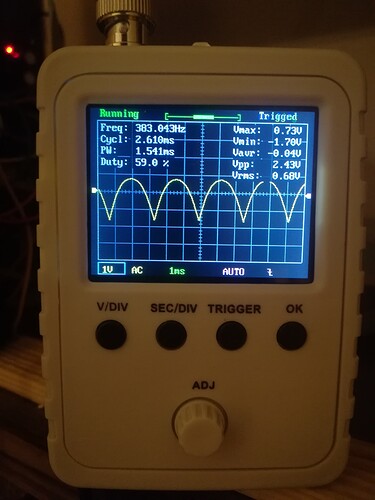
it can be like that and then that’s it.
the Triangle is,i don’t know how much volume percentage less than the Square, so it seems logical that the Sine is even lower, but hey it’s a bit much anyway, I might try some changes tomorrow , thanks guys 
This is the stripboard I mentioned. Same as yours really. I agree with @analogoutput and would start with changing the values of the divider resistors at the output.
thx, values much the same to Thomas Henry’s schem that @analogoutput posted
btw, i don’t understand the utilisation of a double switch for the Sync (the 3 ground ?)
My next build session will include this stripboard. I’ll let you know how I get on.
Yes the sync switch could be a single with just ground on the sync jack I guess. The design is not mine as I mentioned.
I use doubles for grounding guitar circuits a lot. It may be overkill but I’ll keep it for now.
I’d be interested sometime to know more of the role of grounding jacks and switches in modular if anyone knows a good resource or is up to explaining.
Here’s another tri to sine converter, from Kassutronics:

TRI_RAW comes from the buffered triangle output.
This page has an overview of triangle-to-sine converters:
http://www.timstinchcombe.co.uk/index.php?pge=trisin
The two methods mentioned in the thread are “Overdriven differential pair approach” and “Middlebrook & Richer JFET-based method”.
Thank you @fredrik this looks useful.
Nice!
Also, I love pages that say at the top
!! Under Construction !!
Page is very draft and contains much
guff that needs fleshing out!
and at the bottom
[Page last updated: 01 Mar 2015]
I output my triangle to a x2 ompamp amplifier to get the output level I want, like this:
Vto comes from the 3340, TriangleOut goes to output jack.
It is easy to add something like this to the sine as well.
The opamp the circuit you posted is configured as an instrumental amplifier. It is possible to change the output level, but I think it easier to just add another amplifier.
Changing resistors can change output level. Making R13 bigger will result in a lower signal, making R14 bigger will result in a higher signal. Try to keep the resistors between 10k minimum and 500k maximum, to minimize current flow. Too high resistors will increase chance of your circuit to pick up unwanted signals.
thx @ThijssjihT !..
I wanted to ask: with regards to the loudness of the Triangle and Sine outputs, did you happen to take a look at them on a scope, or is it just they sound quieter? The reason that I ask is that Triangle waves are simply not as loud as a square or saw wave of the same amplitude, and Sines are even quieter. This is because square and saw have more harmonic content, which means literally they are made up of bunches of sine waves at integer multiples of the fundamental, triangles are too, but less of them and lower amplitudes. So if the sine just sounds quiet, it may just be that it is a quieter wave.
Yep, TRI and SINE sound quieter normally, and your understanding of why is also correct.
I used the Thomas Henry version but it only works halfway. The top of the wave can be adjusted to sine but the bottom stays triangular. I checked everything but haven’t find the issue yet. Do you have any tips what could I be missing? I’m using +/- 12V.
Looks very much like the problem discussed here
where it appeared the problem is that the triangle wave had a DC offset; it needs to be centered on 0 V.
By the way, this
is similar to what Wilson says in his VCO writeup, and it infuriates me. It may all be true but it’s absolutely useless unless you know what to listen for. I don’t know how to identify “minimal harmonics” by the sound. In fact while adjusting the sine on my VCO, I found the apparent tone quality varied if I turned my head relative to the speaker. In the end I settled for something fairly sine-ish looking on the scope.
Wow, thanks for the super fast reply! That must be it, I completely missed this thread. I’ll try this tomorrow but pretty sure it’s the same issue.
Yep, 10uF with 10k solved the problem! Thanks a lot again!
Glad you made it work! I just designed a stripboard layout for it since I’d like to slap it into my VCO as well 
Where did you add the 10uF and 10K in the schematic or what components did you change them to?


