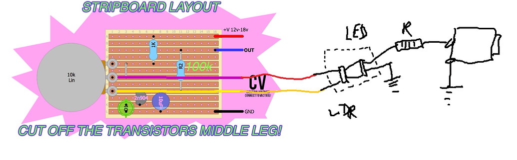
the vactrol is part of the cv with the jack of your SSO circuit, and afterwards with an external LFO you can send impulses by the jack which will make your led flash and therefore let the current flow through the LDR , therefore will increase the pitch of the potentiometer of the VCO (SSO)
3 - if you want add more CV make more vactrol with CV input jack, but maybe already try with one
the same things for CV to the filter and the CV of what you want add a vactrol on a pot like the pic
4 - CV you have already it now and it can work with a sequencer, but for gate it’s more complicated
So what if I want to add CV to the filter? Where should I place it?
BASICALLY THE SIGNAL CHAIN IS OSCILLATOR OUT> FILTER > PASSIV MIXER and then audio out, all on the same board.
The pot thingy on the CV is very cool! I’ll do that!
And one last question, what determines wether a CV is an input or an output?
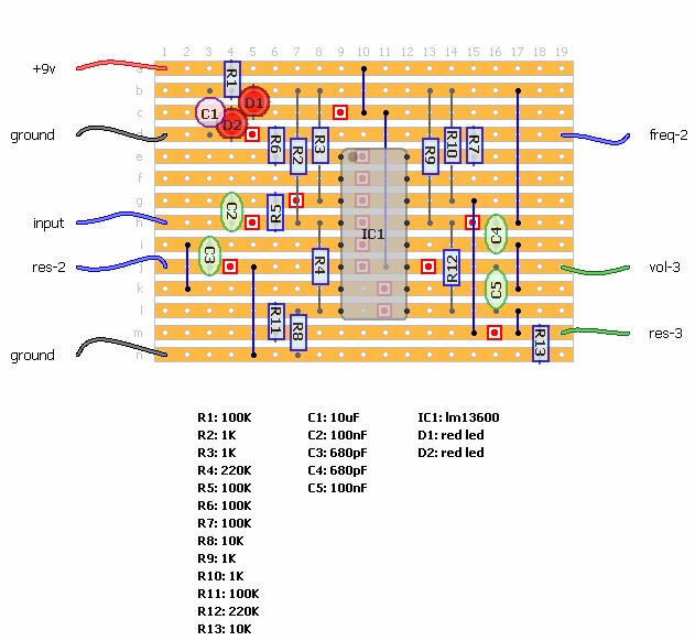
ok it’s a RC filter (think it’s a passif one not a big filter so it’s normal that it change not a lot the sound)
for add a cv put a vactrol on the pin of the pot , you don’t can to make a mistake there is only 2 (2 and 3 are connected)
and in modular all the jacks socket name CV are CV input (on VCO, VCF, VCA … ), exept for some module like Sample and Hold who can send CV for exemple
@Dud Thanks man, big help!
I’ll do this in a bit and let u know if it works; as LFO I was thinking to do the same oscillator circuit with a big cap and connect the out to the CV in of the filter. Does is make sense?
yes ti’s that
I would rather advise you to try an LFO in the CV of the pitch pot of the SSO, to better realize you, because I am not sure that a CV on this kind of filter is very convincing
@Dud NOT WORKING
I noticed that on my circuit I’m going out directly from the 10k pot central pin (transistor, cap and resistor are plugged on that same row, and not on the third pin), unlike in the layout here. Could it be because of that?
Also, I’m connecting the 2nd oscillator audio out into the CV, is that correct?
The space on my breadboard is finished and I already have too many flying cables and alligator clips around. I guess it’s better to wait for the other breadboards that are coming soon and try to make everything more clear using more space
At this point I’ m thinking to not put filters here and build a separate filter module with maybe 4 inputs, do u guys have some idea on a fairly simple project?
if your pitch pot on your oscillator work
so the vactrol must work (it’s just a LDR with a led together in the black connected to this pot)
what value have you test for the led of the vactrol ? (1k is good)
and after with what have you send curent in the CV in ? (if you have a resistance of 1k on the positive leg of the led : you can check it with a 9V battery)