I’m building kind of a bench multitool for testing kosmo modules. So far, it consists of 5v/+12/-12V PSU outputs, audio amp with a speaker, passive attenuator.
The actual problem I am trying to solve is to provide variable CV out, controlled by a single pot for testing VCO 1V/oct.
When looking up the web, voltage regulator LM317 popped up as a popular choice but I’m not sure if this is the right approach for 1V/oct application. No need for precision in my test setup.
Would you mind sharing your ideas, how this can be solved in a simple, straightforward way?
If you just need a variable voltage controlled by a knob, you can use a simple voltage divider, maybe a 10k pot in series with a 2.2k or so (maybe 3.3k) resistor, connected between +12 V and ground. No real need for a separate regulator. (+12 V → 2.20k → pot → ground)
If you worry about the +12 V being not constant enough, e.g. sagging a little when you connect a module that draws more current, you could use a regulator. Simplest probably is an LM7809 which will give you 9 V. And then a 10k pot with a series resistor, in this case I’d use something smaller like 1k.
Maybe a precision resistor ladder with a follower for buffering will give you the 1v/Oct and the 12 steps between each octave, perfect for testing 1v/Oct tuning.
In that case you would want a precision voltage reference, rather than the +12 V rail or a +9 V regulator. For 1 V/Oct calibration you need something approaching 0.1% precision.
I agree a good precision of regulation is required, but really looking at a lot of old analogue synths they had nothing better than 78 series regulators in them.
I think a separate regulation rail would be useful to avoid dip from the main rails, I’m pretty sure I’m using a 10v reference in my Source clone synth and that’s pretty stable.
For a testing jig, I’d take two 12-position rotary switches, and wire them both as precision voltage divider ladders from a voltage reference (eg an lm4040). Buffer them each, then sum them both with the appropriate gains to get 1/12v per position on one, and 1v per position on the other (semitones and octaves). Add some trimmers to the gain resistors for calibration.
That being said, I’d never actually build this. This tool would be equally accurate as the 1 v/ovt input circuits on my modules, so how could I use it for calibration? A keystep does this job just fine…
@TimMJN
I have Kosmo 1222 VCO with rotary voltage divider ladder in my case. I also have a beatstep, however I was looking for something very simple for testing without the need of additional modules or hardware.
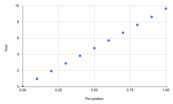
Are you looking at a 10k pot going to a 100k module input? But that should be quite close to linear with a linear pot. Not sure what you’re plotting here. This is what I get assuming a 10k pot, 2.2k fixed resistor, and 100k load:
What is it you’d like to test? My interpretation of testing 1v/oct is "does exactly 1v difference in cv correspond with exactly 1 octave difference in pitch? ". In that case, you need to be able to accurately generate that “exactly 1v”. It’s not impossible, but not trivial either.
If you just want to generate a cv by twisting a pot and hear the response, sure a simple voltage divider from the supply rail will do. But I don’t think it will be accurate enough to guarantee the tested module plays to a conventional musical scale.
Again, I don’t quite know what the use case is. I’m thinking about calibration of the 1v/oct input on eg a 3340 vco, or development of new vcos. Maybe I’m overthinking for your case.
I got me some of these 2.5 and 5V (LM4040) to make me some kind of reference to calibrate modules.
My idea was maybe to do like I did when calibrating various instruments when working at RIFA back then. Check the linearity by applying stepped voltages in a decade (or in an octave) and then check the range by applying larger steps going from one octave to the next.
Haven’t gotten any further.