Check this vid out:

Its one of the earlier LMNC videos, shows how to make a simple distortion!
Check this vid out:
Its one of the earlier LMNC videos, shows how to make a simple distortion!
@Farabide thx a lot for the answer. Better late than never 
Stay healthy and have a nice day !
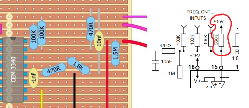
Yeah, that stripboard layout program is pretty shit at rendering things like that. I marked the right pins in the drawing I posted to another 3340 thread:
Hi all!
As many, I’ve made the leap with this simple VCO as my first electronic project. I’ve soldered everything on the stripboard, but it doesn’t work properly  . I’ve tried my best to try to solve the problems on my own, but after a few days of unsuccessful attempts, I am now seeking for your wisdom
  .
.
The main question is: what are the common mistakes I should look for? What is your typical debugging process?
I’ve checked multiple times (before, during and after the soldering) for short circuits in the stripboard with the continuity tool of my multimeter, I’ve found no problem here.
I’ve checked voltage values at each pin of the ICs (I’ve found some suspects, see below).
I’ve plugged an oscilloscope (unfortunately, it’s a very cheap on with no manual, so I am not 100% sure I read the frequencies right. The “Freq” changes depending on my zoom of the x axis, not on the waveform itself. I assume that 10us is for one division, so the frequency should be around 1MHz). I find my waveforms with the expected voltage range (though it is offset), so I assume the VCO is kind of working, but outside of audible range.
Before noticing this, I’ve kind of managed to get an audible sound, but it was thanks to a mistake that I have fixed now: The remaining leg of the course (coarse ?) pot was connected to ground, and I got a pitch only when the pot was at 100% (or 0%, I can’t remember). The pitch stayed a bit, then lowered until it wasn’t audible anymore. I could reset the pitch to audible by moving the pot, then putting it back to maximum (audible pitch, then decay to inaudible). I’m guessing it was the 10nF capacitor discharging that did this, but I am not sure.
Now I’ve add the 12V through a 360(ish) resistor to pin 15 and removed the connection to ground from the course pot. I can’t hear anything anymore. Even when I plug a sequencer sending 1V, 2V, 3V or 4V to the CV input, my multimeter reads values between pin 15 and ground that I find weird (a few dozens of mV, positive or negative depending on how I turn the course pot). This is my main suspect for now, but I don’t know what kind of voltage I should expect between pin 15 and ground. Do you have any ideas?
Do you have other suspects that can cause this high frequencies? I hope you do!
Cheers,
All that resistor to 15V does is it adds an offset to the total control voltage. Some designers like to get something like middle C with no CV going in, and then use negative CV for lower notes; some like zero CV to be the lowest note and then just add positive CV to raise the pitch. It’s up to you whether to add that or not, but it should not be the source of your problems as long as the sum of your CVs is sufficient to bring the pitch into (but not beyond!) the audible range. As for the resistor value, 15V into 360k is equivalent to 4.1667V into 100k, I think (I’m not fully awake yet, check me on this) so raises the pitch by four octaves and a whole tone. The equivalent with 12V would be 288k.
If your scope pictures are correct, you’ve got something going on at 114 kHz, so raising the frequency is not what you need to be doing!
The coarse tune gives you a range from just under 1 Hz (~A-5) to 3100 Hz (~G7) on its own, so feeding in more via fixed resistors is kind of pointless. A bit more here (including chart!):
(ok, in the stripboard layout the pot is a variable resistor, not a voltage divider, so the low end will differ unless you ground the other pin; see here for a discussion about that.)
I assume it is not very interesting for most of you, but I just wanted to say that I finally achieved to have this working My problems were a resistor connected to a wrong pin, and bad soldering connections. So if you are a newbie like me and stuck with a non-working stripboard, be sure to double-check that all the components are in the right place, and that you heat your soldering iron properly (350°C) to get working soldering joints!
Well done. I hate stipboard and breadboard, never got on with them…
I am very happy for you. I’m still a beginner with all the stuff and I can only say check check, double check and then check this double. And work slowly, calmly and carefully. I think each of us is excited and thinks “oh, such a small PCB can be made quickly, at least in 2 hours I can play around with it” … I had to learn very quickly that this method did not work and I had more time afterwards cost as if I had worked carefully and slowly. And as soon as the first weakness occurs, stop immediately. Tomorrow is another day and you will be twice as happy!