MECHANICAL design aid. for ondes martenot like button

Good evening, synth folks.

After completing the build of my drum machine, i’ve decided to make an ondes martenot clone.

Right now i’m at the planning phase and i’ve hit a roadblock with the touché d’intensité design. Therefore, i’m looking for inspiration, design aid, directions, anything that could help really.

The touché d’intensité is a button that works like a potentiometer. it outputs a CV based on the height of the button. The main design elements of this button are the following: some sort of device that returns the button to its original position after being pressed, a device that limits the button’s movement to the intended path and a device that converts the mechanical motion is a variation of voltage.

I’ve identified a couple of routes that i could use to build this button and i’m going to briefly explain them here.

The original ondes’ solution can be seen in the image below


I believe it is using a short linear spring as the return device, the spring is connected to a stiff wooden piece where the button is located, the geometry limits the travel path and a leather pouch with gunpowder(?) is used as the device to convert the mechanical motion in to a variation of resistance.

The ondomo, seems to use a simmilar solution, although it’s difficult to say for sure with only this image as a source.

The company softwire developed an eurorack compatible module with a touché d’intensité like button.


They use a completely different approach. The return device is a combination of two traction springs, two slider potentiometers

peform the double duty of making sure the button travels a set path and convert the mechanical motion into a variation of resistance.

Having consider the previous implementations i’ll talk a little bit about what i’ve tried so far and what i’m considering for my design.
Using a known device to convert mechanical motion to a variation of resistance seems to be the best approach. For that we have a linear slider potentiometer and a regular turn potentiometer. Another possibility is to use a hall effect sensor with a permanent magnet to create a varying voltage with the strength of the field crossing the sensor. So far i haven’t decide which of the designs to go with.

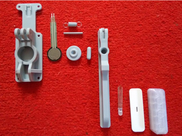
For the purely mechanical part, i’ve made a 3D printed prototype.


image
This was printed with PLA plastic, which is not ideal, and exhibited some spring behavior. But this specific design wasn’t able to provide the height variation necessary. Means to couple this button’s movement to drive the slider potentiometer and regular potentiometer have been considered.
For the slider, a simple square hole with the correct dimentions should be enough. For the regular potentiometer, i’m using the gear like shape of the knob to interact with a hp printer belt. Surprisingly, they fit perfectly. As of yet, i don’t have a hall effect sensor so i can’t make any tests with it, the model i’m considering to acquire is the AHA95.

What i’m considering for my next steps:
Re make the 3D printed piece but with longer and thinner arms. I have other design for 3D printed pieces that i’m considering as well.
button4
This one trying to emulate the original ondes design. Increasing the number of wiggles, should increase the elasticity. For this guy, it would be difficult to implement the slider potentiometer but maybe the regular would could work like so

Well, this is it. Any help is appreciated. Thanks for reading!!

3 Likes

I have been experimenting with building some pedals one thing I have noticed is that if the pedal pivots from one end the rack needs to be curved or pivot because the pedal or button in this case doesn’t travel straight down it pivots which slightly changes the over all length .in this application it may be short enough were it won’t cause any issues.

Trying to use an approach closer to the original design.

The gunpowder thing is probably a lot closer to the truth than some people might suspect. Gunpowder manufacturers needed a source of finely ground high quality charcoal which would be mostly carbon. If you’ve ever used a rotary dial telephone you have used a carbon microphone.

You might want to look into strain gauges.
A quick search shows that they start at $0.60 (up to several hundred dollars, so chose wisely).

I was going to suggest Force Sensing Resistors until I looked at their price. Boy howdy are they spendy…

Have a look at my design for the Touche control in my ‘Ondes framboise’ digital Ondes Martenot emulator. The physical components are on Thingiverse - Ondes framboise - a digital Ondes Martenot emulator by clarionut - Thingiverse. It uses a cheap pressure-sensitive resistor and works very well, but is distinctly non-linear. This is fixed in software in the Ondes framboise.

Got that part printed

But i ended up making the spring too weak. it ended up unable to return the potentiometer.

even after drenching the thing in wd-40.

I’ll try to redesign the part to increase the spring strength and try again.

I’ll also investigate the use of strain gauges.

1 Like

Based on reading about Maurice Martenot’s original Touche design, and my own experiments with the Ondes Framboise (I’ve never had the chance to play a real Ondes unfortunately), I think the Touche should respond primarily to pressure rather than explicit movement. Otherwise the short, percussive attacks which an Ondes can produce would not be possible. This may rule out using a geared potentiometer as the variable resistance element for a truly Ondes-like Touche as it can’t react that fast. YMMV of course, and I hope you find a solution that works well for you.

1 Like

Interesting insight. I haven’t thought about it. I looked at the Ondes Framboise but i couldn’t figure out the mechanism :frowning:

I’ll try to get my hands on a pressure gauge.
Try to adapt the previous design (3d printed spring and panel support) with a pressure gauge.

In case it helps provide some food for thought, here’s a diagram of the assembled Touche from the Framboise construction notes document on Thingiverse:


The pressure sensitive resistor sits in the base sandwiched between two disks of thin rubber underneath the green ‘piston’, with its tail pointing to the right (the little clip at the extreme right holds a Dupont connector). I found my resistors needed too much pressure to be comfortable to use if placed directly under the Touche button - the current position was identified by trial and error.

Good luck with your experiments!

2 Likes

I have a couple more questions…

What circuit did you use with the strain gauge? wheatstone bridge?

And, do you think these guys could achieve good results?
image

I used a very simple circuit - the force sensitive resistor is connected between ground and the channel 0 analogue input of an MCP3008 ADC chip, with a 4k7 pullup resistor connected between the same ADC pin and the 3V3 supply. There’s a 100nF ceramic capacitor in parallel with the force sensitive resistor near the MCP3008 to decouple any high frequency noise. The Ondes Framboise construction notes document on Thingiverse has the circuit diagram for the analogue inputs on page 8.

I’m afraid I don’t know anything about the device in your picture - is it a force sensitive resistor or a strain gauge? I used one of the round force sensitive resistors as illustrated in this picture on Thingiverse. Hope this helps!

Little update.

used a metal arc saw as a spring.

3 Likes

In this video i demo the button with a monosynth.

next step is try to make a button with a pressure sensor.

1 Like

Ended up mirroring the potentiometer.

With this i was able to get the quick transients i wanted.

Also i forgot to mention that i’m using a logarithmic potentiometer.

1 Like

Uploading some 3D files on request.

https://drive.google.com/drive/folders/1bxHf_wS5j9o54bY3ALhhINDbAt1dZLbc?usp=sharing

1 Like