KiCad import works only for XML files produced by more recent versions of Eagle… but fortunately that’s what we have here, and yes you do get both the schematics and the board layouts.
Interestingly, at least on the one I’ve looked at, he’s using the Eurorack 16 pin power connector. He’s not using the +5V bus, fortunately, but he is using the CV and GATE pins, which I’ve never seen used anywhere else. Can they be ignored and a 10 pin connector used? My guess is yes but that’s just a guess.
Also he’s labeled the power buses ±15V, not ±12V, so I don’t know if they’ll work on ±12V without modification. Maybe he addresses these things in his video, I haven’t watched it yet.
Anyway, yes, you can get the files into KiCad. You also don’t absolutely need to, if you want to make the PCBs you just need the Gerber files and I presume that’s what all those “.s#1” etc. files are. If it were me I’d absolutely go with making PCBs rather than trying to come up with stripboards. They’re cheap at places like PCBWay and even cheaper though in my experience not as good quality at JLCPCB. Even at PCBWay for a board under 10 by 10 cm it’s under $15 for five boards if you choose slow shipping or under $25 for DHL which is not bad even if you don’t have four friends to share them with.
This is great news!! We could make a github repo with “our” kicad versions of the boards where we can make changes necessary for 12V and only use 10 pin connectors etc. Anyone interested?
Cool, though if you just want the boards you probably can use them as is — if any parts need swapping for ±12V that isn’t a board change and again I’m just guessing but I think you could just install a 10 pin header for the power and be good to go.
Actually those files aren’t Gerbers, not sure what they are. So to make PCBs you do have to open the board file in either EAGLE or KiCad (or whatever) and generate the Gerbers from there.
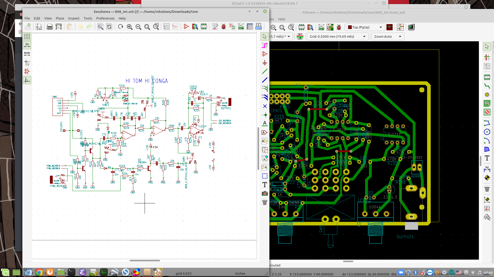
On closer examination it looks like he does use the CV and GATE lines on the 16 pin header to control these things, but he does provide pads on the boards where you could wire a connector instead. I think.
On the next module I looked at the power buses were labeled ±12V, maybe the ±15V was just an error or a one-off thing.
I’m working on a couple of different boards with assistance from @CTorp and @d42kn355. I am planning to get some boards made for some of the 808 voices. (The first one will be the hi hats.) On all of these boards and a few others I’m working on I have been setting them up like Sam did on the Performance Filter where there’s a 2 pin molex connector going from the board to the panel mounted jacks. This way it’s versatile and because the boards are much smaller they will be cheaper to make.
So maybe what I’ll do then is get a tally to see about how many people would be interested in them and will put an order together. There’s another freestanding 808 project that I am also looking at that is a desktop unit with 3.5 & 1/4 ins and outs. However, I think I’ll start with the Eurorack conversions of these modules first.