Designing a DIY VCO

I’m designing a new VCO because I only have 1 in my rack so far and I’m not happy with existing designs I’ve found.

The goals are to have good thermal stability, to be simple enough to be built on stripboard and to avoid exotic components.

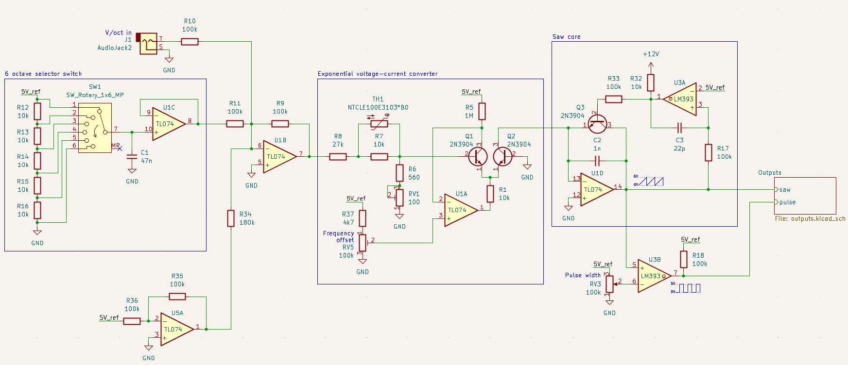
Here’s what I’ve got so far:


The expo converter and temperature compensation is described in these articles by Rene Schmitz and North Coast Synthesis:

The oscillator core is pretty much the same as the one described by Aaron Lanterman in this video, except that I’m using a BJT as the discharge switch. I actually started with a topology like the one Kassutronics uses here: Kassutronics: VCO part 1: core , and experimented with ways of making it work using a BJT in Falstad until I ended up with the circuit I currently have. Here are the simulations from along the way:

To figure out what values to use for the resistors surrounding the NTC, I created this tool: https://tempco-playground.sandelinos.me , which can be used to play around with the values of the surrounding resistors and see how the sinked current varies with temperature.

The wave shaping and output sections are pretty standard stuff. Here’s the simulation: https://url.sandelinos.me/wave-shapers . Instead of removing DC offsets using capacitors, I’ve taken advantage of the 5V voltage reference to scale them to ±5V, which helps avoid distortions that might become present if using the VCO at LFO frequencies (although I’m not sure if the core itself will actually work at such low frequencies yet).

4 Likes

When writing this post, I was in a bit of a hurry so I left out some info. I’ve now updated it with a bit more details. Most of my time on this project so far was spent programming the tempco tool and playing around in Falstad on my lunch breaks at work and on the bus. The plan for today is to match some transistors and start breadboarding to see how it works out in the real world.

1 Like

Also I’m not yet quite sure what features to add. An exponential FM input is a must for vibrato and stuff, but what about linear FM?

PWM CV with an attenuator is also important. I could save 1 knob if I connect the switching pin of the PWM input jack to 5V, so it works as a PWM knob when nothing is plugged in, and as a CV attenuator when a cable is connected to the CV input, but it would mean not having a way to offset the PWM when a CV is plugged in…

2 Likes

Awesome stuff! I was waiting for someone to pick up on the Schmitz/Skala contributions and work them up to something like this.

I was about to ask for possible features, but it’s good that I waited and you added the update. Yes, PWM control with an attenuator if possible and exp FM. Linear FM and Sync as an option if you can be bothered. If I could come with a wish list:

  • Triangle, linear FM, and Sync could be options that one could leave out (which means that any associated op amps with those should be on different ICs)
  • If one attempts a layout, I’d love to see a single PCB, max 100x100mm, with headers for all panel connections so it can be used with any format and/or jack/potentiometer types.

I brought some mf58 NTC tempco’s some time ago with the intent to build a vco but never got to it, partially because I never did find a good guide to figuring out the correct circuit, I’ll definitely check out your calculator encase the drive to make an analog vco strikes me again (and it probably will)

I did note you might have omitted a fine tune control? I suspect you will end up needing/wanting one.

1 Like

I did note you might have omitted a fine tune control? I suspect you will end up needing/wanting one.

Yes I’m planning to have a potentiometer with a roughly 1 octave range, like the #1222 VCO does, but haven’t yet gotten around to adding it. Still not 100% sure if that will be fine enough to be able to set the frequency with enough precision or if yet another knob with even more precision is needed.

I started breadboarding the circuit yesterday, but the saw core is a bit glitchy around the falling edge, so I’ll have to figure out if I can fix that somehow or if I will have to replace the BJT with a FET.

If one attempts a layout, I’d love to see a single PCB…

Regarding boards, my only plan is to create a stripboard layout, probably with the expo converter + core on one board and the triangle shaper + output amplifiers on another. The kicad schematic files will be available at Sandelinos/VCO: DIY Eurorack VCO module - Codeberg.org so if someone wants to fork it and make a PCB they can.

I know there are a lot of solutions using NTC TempCo solutions, but there are some disadvantages.

That’s one of them. The physical behavior / response curves of NTCs or PTCs are hardly the same like the underlying transistor array of the expo, so you have to do research and experiments to find similar response behavior.

What I don’t understand is why designer don’t take over the control over the process and ensure a definite thermal environment instead of reacting to external temperature drifts?

So I decided to use an oven solution for my VCOs. You don’t need to do any research, any temperature - current computations, any special parts, no NTCs, just an old non-contact thermometer for babies.

The VCO core is online in a few seconds and stable independent of any external temperature drift, usage time, on time etc.

When I cloned the Oberheim SEM I built two versions of the VCO core to compare, one with the original NTC compensation and one with a heater-fever - approach. Guess what was the result.

The NTC solution showed the same instable behavior like I was reported by an owner of an original 4-Voice. I was told from other sides that there are even kits to improve thermal stability of Oberheim VCOs by replacing opamps, removing sockets and other stuff.

The heater solution on the other side is stable in a few moments and stays stable. It even works with SMD arrays, what might be a problem for NTC compensation as temperature flows off the underlying PCB when surface mounted.

Here the corresponding heated expo circuit of a 3046 array:

Tr6 (HEATER) and U24B form the oven. U24A is the current sink, and CQ1 of the 3046 array is the mirrored voltage for the saw core. The temperature adjustment is done with Tr6.

Here the demo video of the temperature setup of my Oberheim SEM VCO clone to +39.0 degrees centigrade.

Heater_Video

I might be wrong, but I prefer taking over the control over the temperature environment actively instead of the REactive usage of NTCs.

2 Likes

I did consider the heater approach in the initial planning stages, but decided against it because of the significant power consumption and because transistor arrays are an exotic part. The only non-“jellybean” part in my design is the NTC, which is much easier to acquire than transistor arrays. Seeing that Rene, Kassu and Skala have had good results with NTCs and the predictions from my tool looking good makes me pretty confident in this direction, although how well it ends up working in real life remains to be seen.

1 Like

What’s wrong with the Thomas Henry 555-VCO? You needn’t re-invent the wheel. It works really well on stripboard.

5 Likes

The Thomas Henry 555 VCO is nice, but it’s not that simple, and takes a lot of space on stripboard. Also the PTC tempco resistor it uses is hard to find and expensive.

Why stick to a 14 year old design, when you can design something that fits your situation better?

1 Like

Ah ok. I see what you mean. Btw, the TEMPCO it uses is out of production but Thonk still sells them. In fact they have a sale on them. I ordered an extra 10 pieces so I’ll have stock for coming projects but if anyone needs these PTC’s I advise to move quickly.

1 Like

Sadly, thanks to Brexit, for anyone in the EU the price+postage+VAT+customs is a little steep.

For 10 pieces, Thonk price+postage+VAT+customs duties+handling fee to an EU country is about EUR 45…

For comparison, I can get 10 pieces of AS3340 locally for EUR 52.70.

2 Likes

It looks like they’re getting rid of the last ones they have and once those are gone, they’re gone so the end for these is very near.

1 Like

I’m sure I didn’t pay that much for them.

Yep, it’s the last ones. They’re going to be rare.

1 Like

Progress update:

I was having trouble with spikes before the falling edge of the saw.

This is the circuit where that was happening:

Making R32 smaller would make the spike smaller, but not completely eliminate it. I spent a bunch of time messing with trying to shape the pulse on the base of Q3 without much success until I finally figured out the cause. As the output of U1D rises, that charges C3 so that the voltage on its right side is 5V above the voltage on its left side when the comparator triggers. The ouput of the comparator opens and the voltage on the left side of C3 jumps to 12V, meaning the voltage on the left side of C3 is now 12V + 5V = 17V, which then discharges into the output of U1D, keeping the comparator open for long enough to completely discharge C2. But apparently U1D cannot activate its output transistor to pull the output lower fast enough to sink that current causing that spike. Simply replacing R17 with a 100k so that U1D doesn’t need to start sinking so much current that fast fixed the issue.

2 Likes

The circuit is working well like this, but the frequency range is way too high. The top 3 positions of the octave switch are supersonic. To bring down the frequency I can do one of the following:

  1. Make C2 larger
  2. Make R5 bigger to decrease the expo converter’s reference current.
  3. Raise the voltage on the noninverting input of U1A to do the same thing.

Option 1 would require more current to discharge C2, making the falling edge less sharp, so I’m hoping to avoid that.
Option 2 would require a pretty large resistor which is kinda entering exotic component territory so not a huge fan of that either.
Option 3 I did on the breadboard. Putting around 4.9V on the non-inverting input of U1A put my lowest octave around 30Hz and the highest around 1 kHz, which is pretty good.

However for tuning stability it would actually be better to add a negative offset at the CV mixing stage, because the further you go from 0V on the base of Q1, the worse the thermal stability gets. Just adding a resistor to the negative supply at the summing node of the CV mixer would be bad because any drift in your negative power supply would affect the frequency. Kassu avoided this in his VCO by putting 2.5V on the noninverting input of the CV summing amp, but that approach has it’s own issues.

This seemed a good idea, but later I realized the downside: the negative input of U2b is now regulated to 2.5V, and the VCO frequency changes when plugging in a CV cable carrying 0V.

I could add a negative reference voltage, but it would require another opamp on the main board, which I’d prefer not to do.

1 Like

After a long time of not working on this I finally had some time to get back to this today. I decided to add an opamp to invert the 5V reference to add offset in the CV summing stage so that the range of voltages at Q1’s base is closer to 0 giving better thermal stability. That alone didn’t get the frequency low enough for my liking though, so I also added a trimpot to add a voltage offset to U1A that can be used to adjust the reference current of the expo converter.

2 Likes

A bit more progress today. Added a sync input:

Originally I was using U3B for the saw to pulse conversion, but I decided to do that with an opamp on the output board instead so I can use the proper comparator for the sync input.

Here’s a sound clip of me connecting another VCO playing a sequence into the sync in and messing with the octave switch VCO - Nextcloud