That was done with I guess an idealized model of a MOSFET. I replaced that with a model of a real world MOSFET (VN2222LL) and the upward glitches came back, though not as large as before. On a whim I tried bumping the 10k resistors leading to the caps up to 100k and that improved it:

Just one glitch visible here, a little after 80 ms, and quite small.
The pink trace is the EF output. The falling edge is slow, for two reasons. One is the low pass filter slowing the fall time down. The other is, if you look closely at the red trace (the senior peak detector at the end) and the cyan trace (the input signal), the peak detector stays high for more than two clock periods after the input signal stops. That’d be something like 12 ms for a 150 Hz clock. Then that’s followed by the RC decay for around 10 or 15 more ms.
The gray (appropriately!) trace is the ARP 2600 EF output for comparison. It gets down to zero faster, but it starts much slower and shows more ripple.
Then I thought, okay, this is a pretty short (~200 ms) envelope with square edges, how about a longer envelope with slower rises and falls. I tried a ~2 second piecewise linear ADSR envelope… and was shocked. There are more glitches — well, there’s ten times as many cycles, so ten times as many glitch opportunities. But they’re also much larger than the above. Why? No idea.
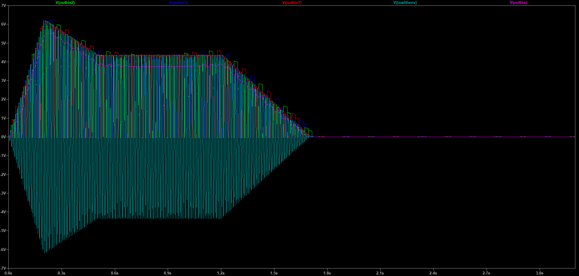
The envelope output is there, in pink, but if you can’t see it, here’s a plot showing just that (cyan) and the ARP 2600 EF output (blue), along with the original input envelope (red):

Which is pretty horrible. Assuming the hardware really behaves like this, I don’t think this design is usable without some way to reset the peak detectors in a clean, glitch free way. Since I don’t have a clue why the glitches occur I don’t have much to go on for a cure. And I’m not sure there’s enough motivation, other than that very fast response time on rising transients.
Added: OK, I can get the glitches down to negligible level, I think. The problem is the reset pulse is too fast. I’d already changed the 1 nF cap to 2 nF, but pushing it up all the way to 20 nF nearly kills the glitches. What bad effects that might have I don’t know.
Now it looks like this:

(Bissell in cyan, ARP in green, input envelope in blue.) There’s a little trash on the sustain but probably not enough to care about. You do see a couple other issues. Thanks to the asymmetric filter there’s no ripple on the flat and falling pieces, but there’s definite ripple on the rising slope. Also, it takes off a bit late at the start and gets to zero at the end slightly too soon: I think that’s because of the diode drop after the peak detectors. Presumably those could be made precision rectifiers, but that adds three more op amps to an already complicated design.
For an envelope like this I still prefer the ARP design. The main advantage for Bissell is on envelopes with a very fast rise.