I decided to breadboard the Harry Bissell envelope follower, which uses a much different method than the common rectifier and filter approach. Bissell’s claim is that it yields fast response with no ripple. The article describing it is here (PDF, on pages 2–3). I know @jos has built an EF based on this but with some quite substantial changes, I was interested in investigating the original design.
I get the general idea of what Bissell is doing here though I certainly don’t understand in detail how it works. There are three peak detector circuits with resets being applied round robin by a clock oscillator and a 4017 counter. The idea is to track and hold the peaks of the waveform cycles, with three peak detectors used to guarantee at least one will be holding a correct peak while the others are being reset. Then the output is the maximum of the three peak detector outputs, with some low pass filtering to remove the clock frequency artifacts.
One thing that I don’t understand at all has to do with the clock speed. Bissell writes:
To ensure that one of the detectors holds the highest peak value for the entire input period, the reset clock period is slightly longer than one-half the period of the lowest input frequency
(Or in slightly less convoluted language, the clock frequency is slightly lower than twice the minimum input frequency.) This makes sense: If the clock speed is too high, the most recent waveform peak may be out of scope for even the most senior of the peak detectors. But Bissell’s clock is a Schmitt inverter with a 10k resistor and 100 nF capacitor. If I use the formula from the inverter datasheet to compute the frequency, using typical values for the threshold voltages, I get about 1200 Hz. And on the breadboard I actually get about 2400 Hz! That is way too high by Bissell’s own criterion (the desired minimum input frequency being 80 Hz).
I built the circuit using Bissell’s component values anyway. Here is a scope trace.

The blue trace on the bottom is the envelope from the B2600 used to generate the input signal. The input signal frequency is about 100 Hz. The top two (yellow and cyan) traces are outputs of two of the peak detectors. You can see they’re all over the place, even in the second half of the envelope where the amplitude is flat so all the peaks should be the same height — so clearly the peak detectors aren’t capturing the peaks. And that’s as expected, since the clock rate is so high: the peak will often be out of scope and it’ll just capture some intermediate value instead. The third (magenta) trace is the EF output, and it looks kind of like the original envelope, but with lots of audio frequency structure and a kink about 1/4 of the way through. The rise time is fast but the fall time is much slower, due to the asymmetric low frequency filter.
Clearly the high clock speed is causing problems here. Maybe it was just an error in the schematic. I replaced the 10k resistor by 100k, bringing the clock speed down to around 240 Hz, still a tad high but much closer. Then I got this:

And now it seems much of the time the peak detectors are indeed capturing the peaks, you can see the correct envelope shape buried in there. But then there are big upward glitches that spoil everything and completely ruin the output envelope. (And yes, those glitches are present on the third peak detector too.)
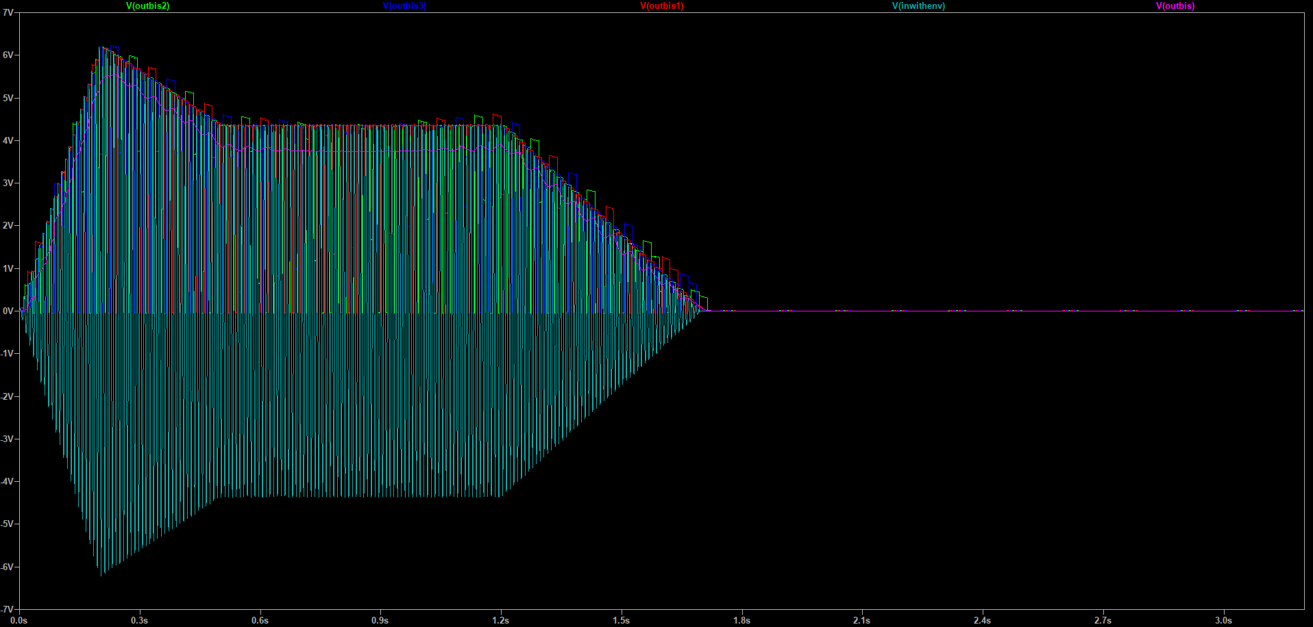
I’d be tempted to chalk the glitches up to some kind of breadboard flakiness, though it’s can’t be that flaky if it’s affecting all three the same way… but in fact it’s not entirely dissimilar to what I see in an LTSpice simulation:

(Click on the image to see it more legibly.) The cyan trace is the input signal — again about 100 Hz, this time with just a sawtooth for the envelope. The green, blue, and red traces are the peak detector outputs. Again you can see they correctly capture the peaks a lot of the time, but then there are times they glitch upward. It looks to me like the upward glitches tend to happen when the reset pulse occurs close to an input signal peak.
So it seems as if the reset mechanism is messing things up, somehow adding charge to the cap instead of discharging it.
Not sure where to go with this. It seems an interesting idea, though I’d say to take Bissell’s “fast response and no ripple” claim with a grain of salt — you certainly do get something like ripple if the input frequency is too low compared to the clock speed, just as you do with a rectifier-filter EF if the input frequency is too low compared to the filter cutoff, and the response to falling transients appears to be no better than the ARP 2600 EF, though it does look like it does much better on rising transients. Which is something, but only if the glitchy behavior can be cured.