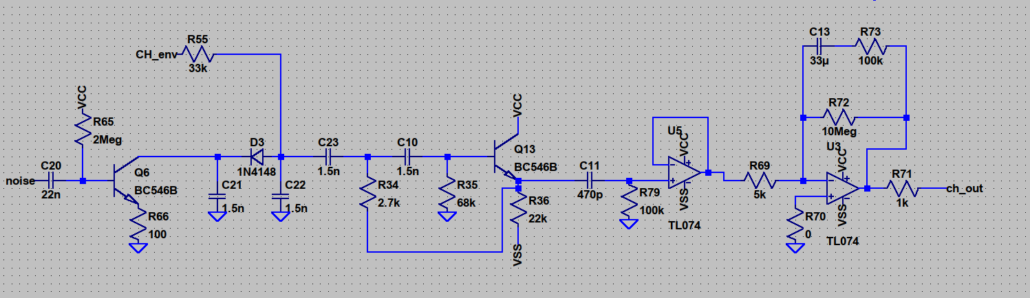
You probably have that but there it is. I don’t see any reason why you would need to add a buffer, there’s 39k to a virtual ground which should not be hard to drive. In yours there’s 100k to ground which isn’t that big a difference. Why is that 100k pulldown there, by the way? I’d say revert to the original and measure the emitter voltage on T12 (your Q13), verify it doesn’t change much when connected to C23 and R54. If it does that’s surprising to me.
Below is my python code (it does not print the values from LTspice, I added them by hand) to compute the frequencies. Any obvious mistakes? why is there such a difference?
In LTspice I used VDD =5V as a well.
#!/usr/bin/env python3

import numpy as np


def cd40106_astable_vibrator_freq(R, C, Vdd=5, Vp=2.9, Vn=1.9,):
    """
    from the dataset
    returns frequency in Hz
    """
    t_a = R * C * np.log(Vp/Vn * ((Vdd-Vn)/(Vdd-Vp)))
    # print(Vp/Vn * ((Vdd-Vn)/(Vdd-Vp)))
    # print(np.log(Vp/Vn * ((Vdd-Vn)/(Vdd-Vp))))
    return 1/t_a


# kohm and nF
R_C_combos_in_808 = [
    [300, 22],
    [270, 18],
    [220, 18],
    [680, 10],
    [560, 10],
    [560, 18],
]

lowest = R_C_combos_in_808[-1]
print("R, C, f, ratio")
for combo in R_C_combos_in_808:
    R = combo[0] * 1000  # kiloohm to ohm
    C = combo[1] * 1e-9  # nF to F
    f = cd40106_astable_vibrator_freq(R, C)
    ratio = f / cd40106_astable_vibrator_freq(lowest[0]*1000, lowest[1]*1e-9)
    print(R/1000, C/1e-9, f, ratio)
What does your LTSpice model look like?
Does it use the same Vp and Vn?
In the datasheet I have it looks like Vn can range from 0.9 to 1.9 and Vp from 2.9 to 3.6.
Maybe try messing with those values?
Just remember, in theory there is no difference between theory and reality, in reality there is…
I use a „standard“ 40xxx library I got somewhere xD The only thing that found I can change is Vdd, so I thought that would determine Vp and Vn, but I should check that!
Whatever Vp and Vn and Vdd are, they presumably are not dependent on R or C. So t_a should be proportional to RC — and for LTspice it’s not:
R
C
f_datasheet
f_LTspice
RC
t_a_datasheet
t_a_LTspice
t_a_datasheet/RC
t_a_LTspice/RC
300
22
186.521
230
0.0066
0.00536
0.00435
0.812
0.659
270
18
253.3
317
0.00486
0.00395
0.00315
0.812
0.649
220
18
310.868
387
0.00396
0.00322
0.00258
0.812
0.653
680
10
181.035
227
0.0068
0.00552
0.00441
0.812
0.648
560
10
219.828
225
0.0056
0.00455
0.00444
0.812
0.794
560
18
122.126
273
0.01008
0.00819
0.00366
0.812
0.363
The ratio of t_a from LTspice to RC varies by more than a factor of two, and is less than the datasheet values by factors of between one and more than two. In particular, for R = 560, f should nearly halve when C goes from 10 to 18, and instead it increases by about 25%. For the other R values the ratio is nearly constant, consistent with different Vn and Vp values, but for R = 560, I don’t believe the LTspice values.
But a few minutes with a breadboard should answer the question, no?
Depends on VDD, for 5 V, Vp is min 2.2, typ 2.9, max 3.6. For VDD = 10 V it’s about double that.
Man! you’re a genius!
I just checked my simulation again and I had different values for C (10nF instead of 18nF) for the R=560k cases! What was I doing? xD
So, now I need to check what’s up with the Vn and Vp in my simulation (and check back on the breadboard!)
Datasheet says Vn can be in the range 0.9 to 2.8, Vp in the range 2.2 to 3.6. Presumably they don’t vary independently or otherwise you could have Vn > Vp, but even so t_a/RC probably has a fairly big range, certainly 0.81 to 0.65 seems possible:
Vdd
5
Vn
Vp
0.9
1.9
2.8
2.2
1.275
0.248
-0.482
2.9
1.839
0.812
0.082
3.6
2.461
1.434
0.703
There’s not enough information in the datasheet to know how likely such a difference from one chip to another is, though. Bottom line is, if the frequencies are critical, then you probably should use trimmers. But in Eric Archer’s schematics it doesn’t look like frequencies are specified, just fixed component values, so who knows what frequencies you’re really aiming for?
You’re probably right, maybe this does not matter at all for the purpose of getting this kind of metallic noise! I also found quite a number of different frequencies for the noise depending on the source, even if they all claim it’s a 808 hihat
I was mostly confused because the simulation did not fit the datasheet.
Now I tested two combination on breadboard as well and they are also different, ofc:
R(kohm)
C(nF)
t_a_datasheet
t_a_measured
t_a_measured/RC
300
22
0.00536
0.00877
1.3287
556
10
0.00452
0.00666
1.1978
I think t_a_measured/RC should all be the same, but with only two values it’s not a great dataset I might test more combination, but maybe I will just leave it at that and hope that it will somehow sound good (maybe I add optional footprints for trimmers for the resistors if there is space).
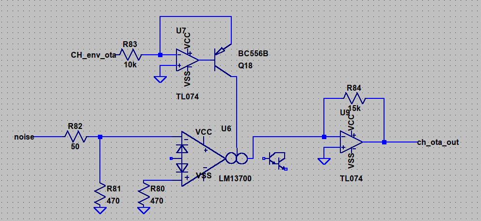
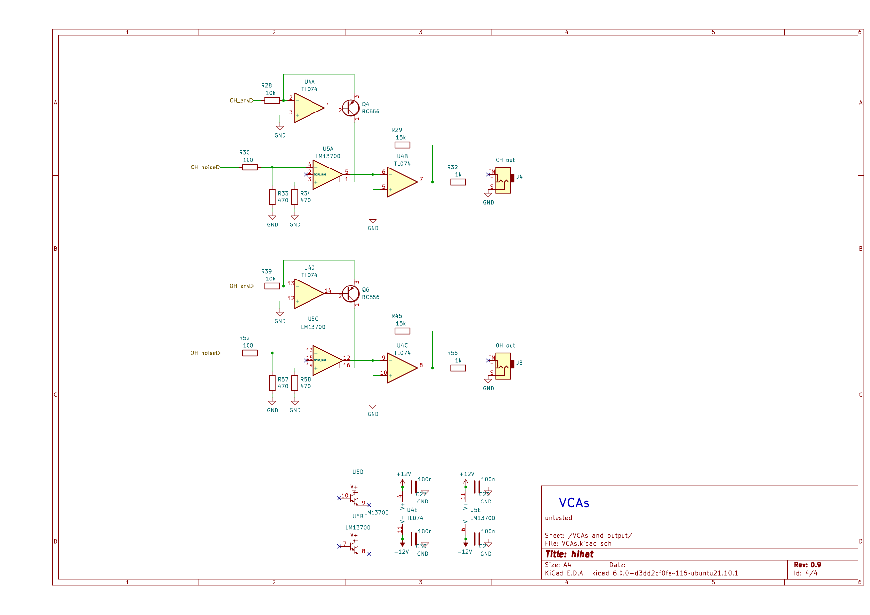
It looks like the OTA is less components overall, but it uses 3 opamp stages (6 for open and closed hihat) plus the OTA, where the original only needs 2 opamp stages (4 for open and closed)
The waveform is a bit nicer (=more symmetrical) for the OTA version, but is that important? Even audible?
your modifications look really nice, Im curious to ear your version.
In my version I think that the decay time is too short, maybe I go modify that but I’m really lazy for moment… ^^
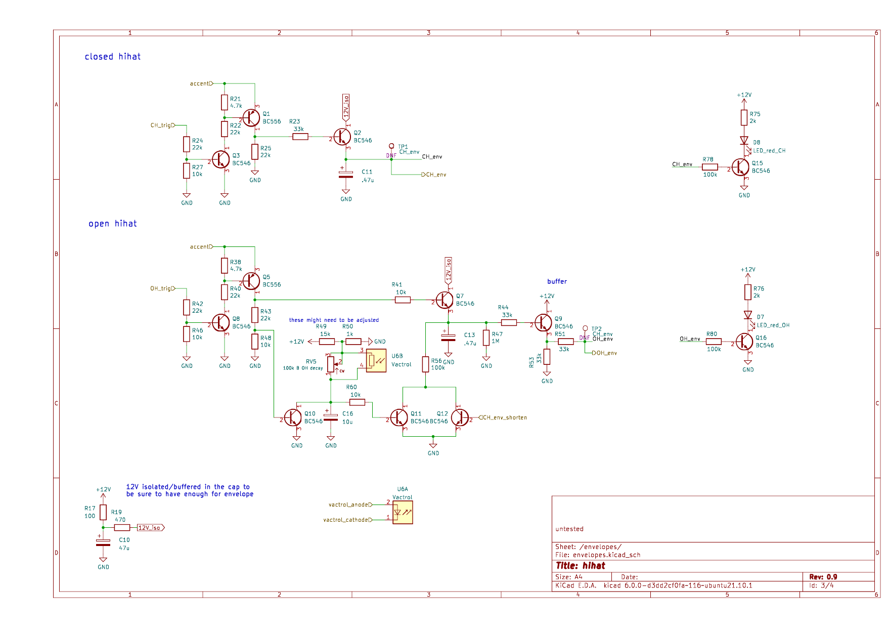
Another issue: I want to visualize the envelope with leds. Very, simple it should just be on as long as the envelope is high, not need for linear relationship, just to have a visual indication of what’s happening. Can I simply use a transistor like this:
Or will this have a low enough impedance that it will change the envelope? I know that I can use an opamp, but that seems a bit overkill… I have used this transistor circuit already, but only for the trigger part of a circuit, but I want it showing the envelope now
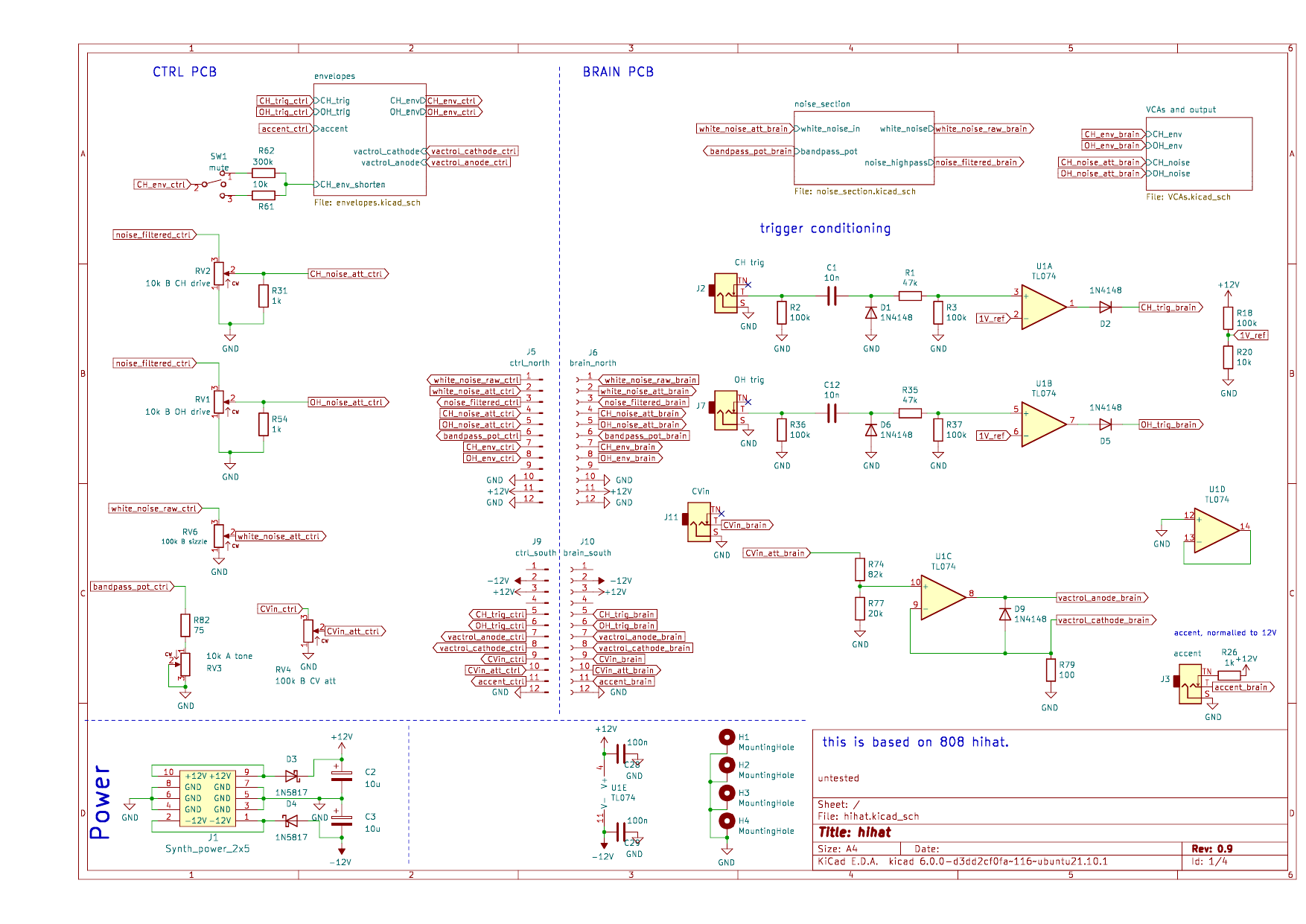
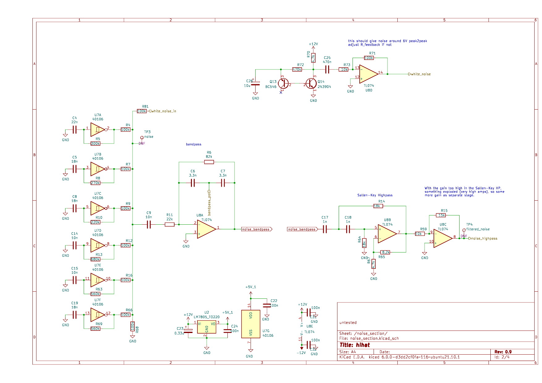
I am pretty far, I think! Here come the schematics. If you see anything suspicious, tell me
I still need to do the pcb and also adjust some resistors to get a good response from the potentiometers,
but I might just socket those (around the VCA and the noise mixing) and then test with the real board… or I might do some more simulations xD
It does work!! Some minor fixes had to be done, the big one was switching the jack sockets for open and closed hat xD
Is it a lot better than the simple 2 transistor stripboard hihat? Maybe…? I guess so, at least it’s a lot louder I will make some demo sounds in the next day and publish everything on GitHub!

 The 100k pulldown is weird, I know, but without it, things are really crazy
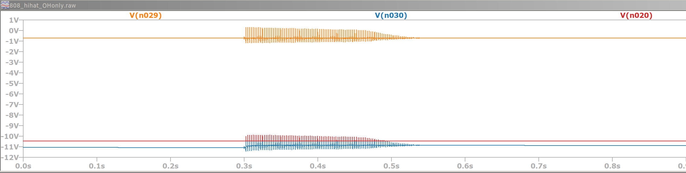


 I will make some demo sounds in the next day and publish everything on GitHub!