That totally explains me getting almost nothing out with the PO-35! 
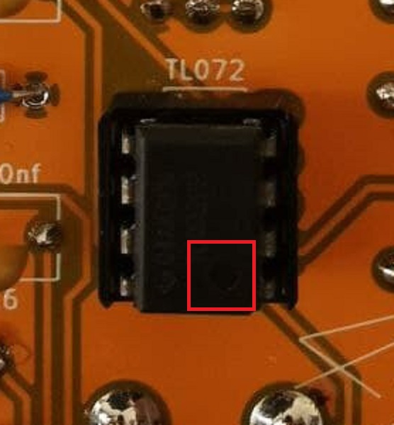
Well after multiple build headaches, I’m throwing up my arms too. First time I “finished” building, no sound AND the LED never lit up. Checked everything then out of curiosity I flipped the chip TL072 around and the LED lit up but still no sound. Signal passes through it just fine when bypassed. Flip it on, no sound, let the tube warm up, still cool to the touch. I guess I’ll try to check the solder on the tube again.
Been reading all the comments but I wish I at least had some signal instead of low volume, ha!
Cheers, guys!
1 Like
UPDATE: Resoldered the tube. Heats up now! Still no signal 
1 Like
seems like soldering of the tube is a recurring problem . maybe use of socket would be better ?
1 Like
That’s my exact issue, I’m beginning to wonder if I bust the tube by soldering it. I checked it with a scope and I’m getting nothing on the output pin so it’s looking highly likely, going to order a replacement tube and perform the fun task of desoldering!
Might also grab a tube socket and see if there’s enough clearance to fit one in there.
the legs to check are the ones going to ground they are always the ones that are a little tough.
soldering the tube down itll take a lot to break it in all honesty. the reasons for soldering
the eurorack safety valves off spurts from the GMSN one that was done after my youtube video were all soldered directly to the board it proved successful to do this, they were a lot more reliable than the socket ones I had which always had a tendency of shaking loose and not working after a number of shows. have valves pointing forwards and also visible (which is a must haha) meant they would be shakey, and also another one I took out and put back in valves all the time which wore out the sockets.
-for the amount of time tubes last (this will likely last longer than you and me as they are not being operated at full operating temperature) it just makes sense to solder them in. they dont need replacing so removing a socket seems a smart thing to do
-socket adds more height to the module ie more chance of knocking it and smashing it.
1 Like
could you send a pick perchance of the back of the board??
also can you see from underneath the tube there is definitely no shorts with the LED pads?
however I know its a source of controversy. so im trying to find things like linked Socket Pins *84 pcs* for 6 x IN-14 Nixie Tubes IN-8-2 IN-16 IN-19 for Clock 788144766074 | eBay
the right size for 12ax7’s. that can potentially be soldered from the back of the module even. that way if people are not feeling confident, and also dont need to worry about the ruggedness of the synth as its staying in one place and hardly ever moves or gets chucked in a van then maybe its a good option
2 Likes
ok I have found these.
these share the same footprint as the valves. if anyone finds local links to their country please share±! I have ordered some to try out. it looks like this will bring the height of the tube to the bottom in line with the panel. near enough the same height as a DIY one. so it might be a good option!
im not going to include this on the webpage until mine arrive and I have tested
also found these but a lot more money lol EIZZ High End Miniature 9pin Tube Sockets Bases For 12AX7 6922 EL84 ECC82 ECC81 | eBay
4 Likes
Sam,
Hopefully legit shipment to the United States - 2x gold plated 9pin bakelite tube socket testing saver for12AX7 ECC83 5670 SED | eBay
-Fumu / Esopus
1 Like
I got these sockets off amazon when I originally put my parts order in for this module. https://www.amazon.com/gp/product/B08JTMKCHQ/ they are of course more expensive than the ali sockets, but they also are delivered quickly.
The tube pins seem to fit very tightly in it and it takes some considerable effort to rock them into place.
2 Likes
not checked mine again , but it was soldered on the Valve. But I was using the TS100 on 400C so it was in and out like a Ninja…
I started building mine up tonight, and I have to say that soldering components directly to vacuum tube socket pins feels very old timey and fun.

5 Likes
As requested a back of the board.
Done a continuity test and there’s no shorts with the LEDs/tube pins that I can detect or see!


2 Likes
cant see anything obvious ( can’t tell you the colour codes on the resistors are correct ) . Try referencing against the schematic and check continuity and values with a meter , there was one resistor that gave a false result in circuit wheni did this.
I can’t see what this looks like on the back, but from the front this joint looks a little sus…
Also are those tantalum caps? if so you’ll need to swap them out for ceramic because tantalum caps have polarity. EDIT: Given the description of working and then not working… that sounds like tantalum caps. I did the EXACT same thing with my build on the K25 LFO. they print those little ‘+’ signs on them so small…

Looks like multilayer ceramics from here. Tantalums tend to be a bit rounder when seen from the top (and do they even make 47 nF tantalums?)
They do, and Mouser would sell you one for $20.80, but it’s non-stocked.
1 Like
I thought that joint looked a little sus too, from the back it looks fine and continuity test is all fine too.
I appreciate the confusion for the tantalum caps too, but not to worry they’re standard ceramic cap