Thanks. It’s one of those articles you stumble upon when your’e not really looking. ![]()
The Yusynth divider does things pretty much the same way, except for voltages. With the Mid century build differing in the way they implement the leds too. It’s all good though.
PS: I forgot to link the elephant in the room ‘Yusynth’, but I’m sure most people got that.
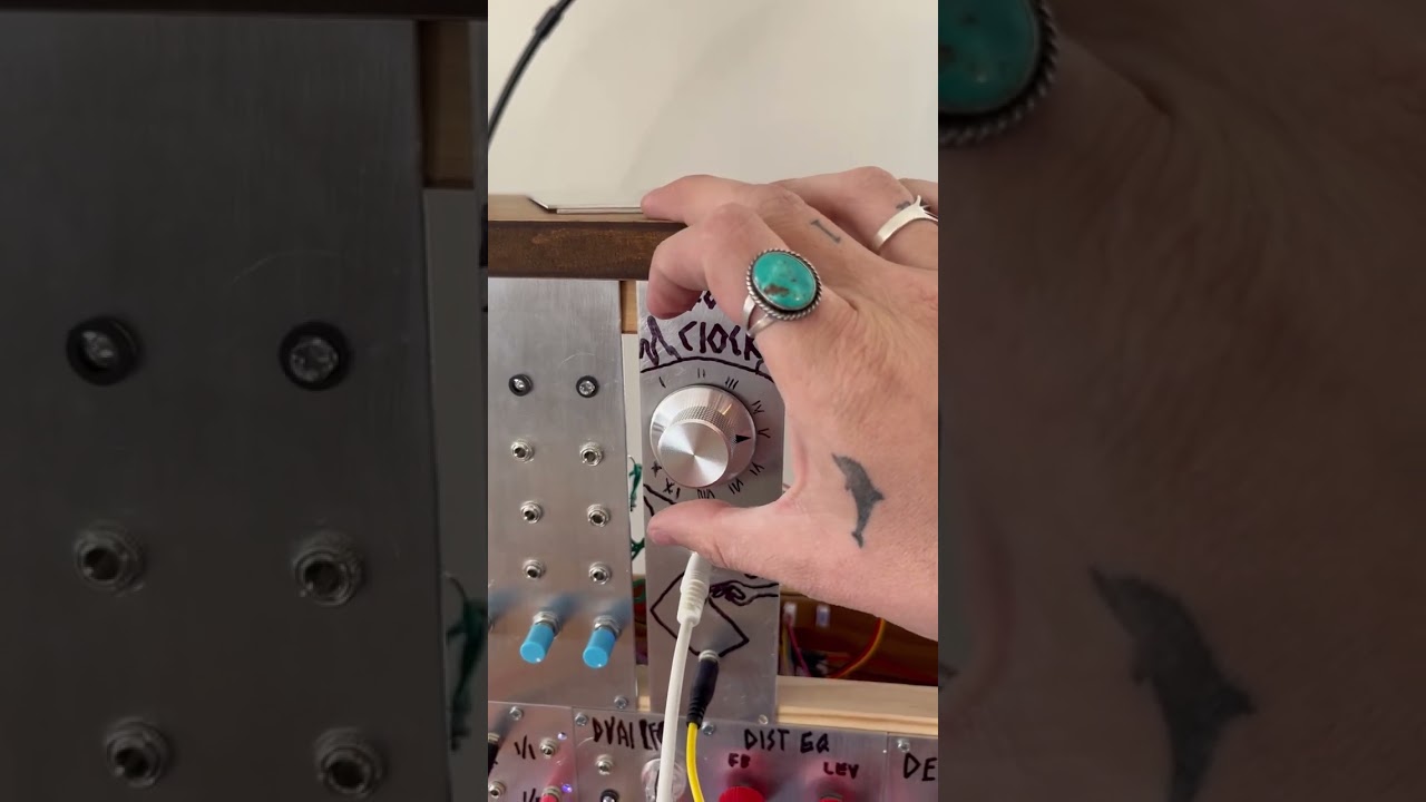
I built it and it works! Very cool and useful module ! Thank you gasboss
My computer is broken so I can’t make a revised layout, but to whoever might want to build this, gasboss edited version is verified .
I have an empty slot on my diy rack and everything but the rotary switch to build the module. I can switch it up with spdt switches tho, so I may give it a shot. Thanks for putting this out!
Ive been experimenting with different ways of doing this. It is possible to make a voltage controlled divider , so far Ive only tried it on a circuit simulator.
I know this has been done before by a guy called Jurgen Haible, I think his name was. He was putting out synth diy stuff just as the internet started to expand into what it has become today, late 1990’s I think.
Do you mean that a control voltage would determine what division the module would output? Is that like Richard’s cv mod for the the Barton Wave Shape?
Not really, in the CV Wave Shaper the CVs govern the amplitude of each division in the output mix.
Ok. Just curious. Thanks Rich!
Yes the CV would determine the division amount.
…
I found an archive based ressurection of Juergen Haible’s work
Here is his take on the voltage controlled divider, a bit different to what I was thinking!
Here is the home page of his legacy site, well worth a look:
